
How to Read an FFT Spectrum: Five Vibration Signatures Every Mechanic Should Know
We break down five key vibration signatures in FFT analysis: imbalance, misalignment, mechanical looseness, bearing faults. Learn what the FFT spectrum shows for each rotating-equipment fault — and why FFT alone isn't enough today.
Article available in Russian
The full article body is currently published in Russian. A translated version is in progress — switch to Russian for the complete text.
Read in Russian
An unplanned shutdown of a large motor at a mining operation means 4 to 48 hours of downtime and tens of thousands of dollars in direct losses. Plus, in the worst case, a chain reaction across connected equipment.
Most of these failures are predictable. The equipment gives warning weeks, sometimes months, in advance — if you know what to listen for.
One of the key tools is vibration signature analysis in the frequency domain. Below we break down what the FFT spectrum reveals for five of the most common rotating-equipment faults, and explain why FFT analysis alone isn't enough anymore — and where SDT340 and Artesis e-MCM fill in the picture.
What FFT is and why it matters
FFT (Fast Fourier Transform) is a mathematical method that converts a time-domain vibration signal into a frequency spectrum. Instead of a noisy waveform, the engineer sees distinct peaks at specific frequencies, each one carrying diagnostic information.
The key reference frequency is 1x RPM — the rotor's fundamental rotational speed. Every other peak is interpreted relative to it: 2x, 3x, and so on.
Knowing how to read these patterns is the foundation of vibration diagnostics.
Five key FFT signatures
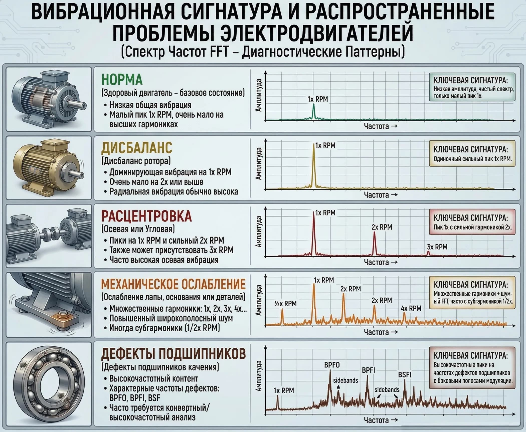
1. Normal — a clean spectrum
Low overall amplitude, a minimal 1x RPM peak, no extraneous components.
This is what a healthy machine's spectrum looks like. A small peak at the running speed is acceptable — it's always present. What matters is the absence of extra peaks and broadband noise.
2. Imbalance — 1x RPM dominates
A sharply pronounced peak at 1x RPM, significantly exceeding all other components.
Imbalance is an uneven distribution of rotor mass. The rotor pulls to one side, generating a centrifugal force that loads the bearings and foundation.
Imbalance rarely appears instantaneously. It builds up as the impeller wears or becomes fouled. If the 1x RPM peak has been climbing from one reading to the next, that's not just a log entry — it's a signal to find the cause.
Typical sources: wear or material buildup on pump or fan blades, balancing errors after a repair.
3. Misalignment — 1x and 2x RPM with an axial component
High peaks at 1x and 2x RPM with pronounced axial vibration. A 3x RPM peak sometimes appears as well.
Misalignment occurs when the axes of coupled shafts don't line up. It's one of the most common causes of accelerated bearing and coupling wear.
Important note: misalignment often develops after the machine has already entered service — due to thermal expansion of the housing, foundation settling, or imperfect reassembly after a repair. A one-time laser alignment at installation doesn't guarantee alignment is preserved six months into operation under heavy conditions.
4. Mechanical looseness — a forest of harmonics
A characteristic "comb" of multiple harmonics (1x, 2x, 3x, 4x RPM and higher), elevated broadband noise, possible subharmonics (0.5x, 1.5x RPM).
Mechanical looseness is any form of insufficient stiffness: loose foundation bolts, cracks in the frame, a loose bearing fit in the housing.
Unlike imbalance or misalignment, there's no single dominant peak here — energy is smeared across many harmonics. The more harmonics with noticeable amplitude, the more serious the problem.
5. Bearing faults — high-frequency components
High-frequency vibration with characteristic fault frequencies:
- BPFO — outer race
- BPFI — inner race
- BSF — rolling element
- FTF — cage
The most dangerous and the "quietest" signature. A bearing fault develops in four stages. During the first two, the vibration spectrum looks nearly normal — until the defect progresses to stage 3-4 with a pronounced amplitude rise.
By the time FFT clearly shows the problem, bearing failure may be only weeks or even days away.
Where FFT falls short
Vibration analysis is a powerful tool, but it has two systemic limitations.
The first is coverage. A typical mining or metallurgical plant runs hundreds of electric motors. Mounting vibration sensors on every one is expensive. Route-based surveys with portable equipment cover 10-20% of the fleet, once a quarter. The rest of the machines run blind.
The second is horizon. FFT analysis detects bearing faults once they've already reached stage 3-4. By then, the window for planned intervention has narrowed considerably.
Both limitations are closed by specific tools.
Artesis e-MCM: monitoring the entire fleet without shaft-mounted sensors
The Artesis e-MCM system works differently from traditional vibration diagnostics. It analyzes the motor's supply current and voltage and uses that data to identify mechanical and electrical faults: imbalance, misalignment, bearing defects, rotor eccentricity, pump cavitation.
It connects to the existing current transformers, with no sensors mounted on rotating parts. This makes it possible to cover the entire motor fleet, not just a sample.
Faults are detected 3-6 months before failure — enough time for a planned repair during a convenient process window. A single avoided major motor failure (replacement cost starting at $50,000) pays for the system.
For route-based surveys without continuous monitoring, there's the portable Artesis AMT Pro, working on the same principle.
SDT 340: ultrasound sees the defect before vibration does
The SDT 340 ultrasonic detector operates in the 20-100 kHz range — frequencies inaccessible to standard vibration diagnostics. It detects bearing faults at stage 1-2 on the dBµV scale, while the FFT spectrum still looks normal.
Where vibration analysis says "everything's fine," ultrasound is already picking up the first signs of degradation. The difference in warning horizon can be several months.
Beyond bearings, the SDT 340 also detects compressed air and steam leaks (for unaudited systems, losses run 20-30% of compressor output), and diagnoses high-voltage equipment for corona and partial discharge.
For metered bearing lubrication, there's the SDT LUBExpert suite. It shows when to lubricate and how much, eliminating over- and under-lubrication. According to SKF, over-lubrication causes 42% of premature bearing failures.
How it works together
| Task | Tool |
|---|---|
| Early detection of bearing faults (stage 1-2) | SDT 340 |
| Continuous monitoring of 100% of the motor fleet | Artesis e-MCM |
| Confirming and classifying the fault | FFT vibration analysis |
| Precise condition-based lubrication | SDT LUBExpert |
The logic is simple: ultrasound signals first, vibration analysis confirms and refines, Artesis keeps watch over what route surveys can't reach. Every intervention becomes planned and data-driven, rather than a reaction to a failure that's already happened.
Summary
Each of the five FFT signatures covered above isn't just a teaching example. It's a pattern by which real equipment reports a problem weeks before failure. The only question is whether you have a system that's listening.
Want to find out how well your current diagnostic approach covers your critical equipment? Contact us — we'll run a technical review and show you where the blind spots are.
KEG TRK is the official distributor of Artesis and SDT International in Kazakhstan and the CIS.
Equipment in this article
e-MCM
Онлайн мониторинг электродвигателей без датчиков
SDT340 - Продвинутый ультразвуковой детектор
Самый продвинутый ультразвуковой детектор для сбора, анализа и трендирования дан...
LUBExpert - Система управления смазкой подшипников
Управление программой смазки подшипников с базой данных, Shopping List и Work Or...
SCOUT Series - Портативные анализаторы вибрации
Портативные коллекторы и анализаторы данных для диагностики оборудования
System 1 - Платформа мониторинга состояния
Флагманская платформа мониторинга состояния и диагностики от Bently Nevada
3500/42M Proximitor Seismic Monitor
4-канальный монитор вибрации для критически важного оборудования
Velomitor - Датчики скорости вибрации
Пьезоэлектрические датчики скорости вибрации для мониторинга корпусов машин и по...