
Поверка и калибровка средств измерений: как выбрать эталонное оборудование
Как выбрать эталонные калибраторы давления и температуры, зачем нужна поверка датчиков и почему её дрейф искажает данные предиктивного обслуживания.
Любое решение по управлению процессом — от открытия клапана до остановки насоса по аварийной уставке — принимается на основании показаний датчика. Если датчик давления или температуры «ушёл» от истинного значения на 1–2%, это не заметно оператору, но система получает искажённые данные и реагирует неверно. Единственный способ гарантировать, что показания соответствуют действительности, — регулярная поверка и калибровка средств измерений с помощью эталонного оборудования, точность которого заведомо выше точности проверяемого прибора.
В этом материале — практическая логика выбора эталонных калибраторов давления и температуры, разница между рабочим и эталонным прибором, форматы поверочных работ и то, почему метрологическая дисциплина — это фундамент, на котором стоит любая программа предиктивного обслуживания.
Зачем нужна поверка и калибровка датчиков давления и температуры
Погрешность измерительного канала растёт со временем даже без видимых неисправностей. Основные причины дрейфа:
- механический дрейф чувствительного элемента — усталость мембраны, микротрещины, остаточная деформация после гидроударов и превышения предельного давления;
- термоциклирование — многократный нагрев/охлаждение меняет характеристику тензорезистивного или ёмкостного элемента;
- коррозия и загрязнение — агрессивные среды, конденсат, отложения на мембране разделителя;
- старение электроники — смещение нуля усилителя, деградация опорного источника напряжения;
- износ контактов и разъёмов — рост переходного сопротивления в цепи термопреобразователя.
Важно различать два регуляторных понятия:
- Поверка — обязательная процедура для средств измерений, включённых в сферу государственного регулирования обеспечения единства измерений (учёт энергоресурсов, экологический контроль, безопасность). Проводится аккредитованной лабораторией по утверждённой методике, завершается нанесением поверительного клейма и оформлением свидетельства.
- Калибровка — добровольная процедура, применимая к любым средствам измерений, включая внутренние технологические приборы, не подпадающие под обязательную поверку. Результат — калибровочный сертификат с указанием фактической погрешности или таблицей поправок, без разрешительного клейма.
Обе процедуры требуют одного и того же: эталонного средства измерения, погрешность которого достаточно мала по сравнению с допуском проверяемого прибора.
| Признак | Поверка | Калибровка |
|---|---|---|
| Обязательность | Обязательна для приборов сферы государственного регулирования | Добровольная, по решению предприятия |
| Кто выполняет | Аккредитованная в установленном порядке лаборатория | Любая метрологическая служба, в т.ч. собственная |
| Итоговый документ | Свидетельство о поверке, клеймо | Сертификат калибровки, протокол с поправками |
| Типичный объект | Узлы учёта, приборы систем безопасности, весы для торговли | Технологические датчики давления/температуры внутри контура АСУ ТП |
| Что происходит при отрицательном результате | Прибор изымается из эксплуатации до устранения неисправности | Прибор может эксплуатироваться дальше с учётом поправки, если это допустимо регламентом предприятия |
Рабочий прибор и эталон: в чём принципиальная разница
Рабочий преобразователь и эталонный прибор решают разные задачи и поэтому имеют разный запас точности. Общепринятое правило — соотношение погрешностей не хуже 1:4 (эталон должен быть минимум в 4 раза точнее поверяемого прибора), в метрологических лабораториях 1-го разряда стремятся к 1:10.
| Категория прибора | Типичная точность | Назначение | Пример |
|---|---|---|---|
| Рабочий преобразователь давления | класс 0,5 / 0,25 | Измерение технологического параметра в контуре АСУ ТП | Смарт-преобразователь 4–20 мА / HART на технологической линии |
| Эталонный преобразователь давления 1 разряда | 0,02–0,05% | Поверка и калибровка рабочих преобразователей и манометров | Эталонные преобразователи давления |
| Рабочий термопреобразователь (ТСП, класс B) | ±0,3 °C при 0 °C | Контроль температуры технологической среды | ТСП/ТСМ в трубопроводе, подшипниковом узле |
| Эталонный термопреобразователь / цифровой эталонный термометр | 0,01–0,05 °C | Поверка рабочих ТСП, ТСМ, термопар | Эталонные термопреобразователи |
Смешивать эти категории нельзя: поверка рабочего прибора эталоном с сопоставимой или худшей точностью не имеет метрологического смысла — погрешность результата станет неопределённой, а свидетельство о поверке не будет отражать реальное состояние прибора.
Оборудование по теме статьи
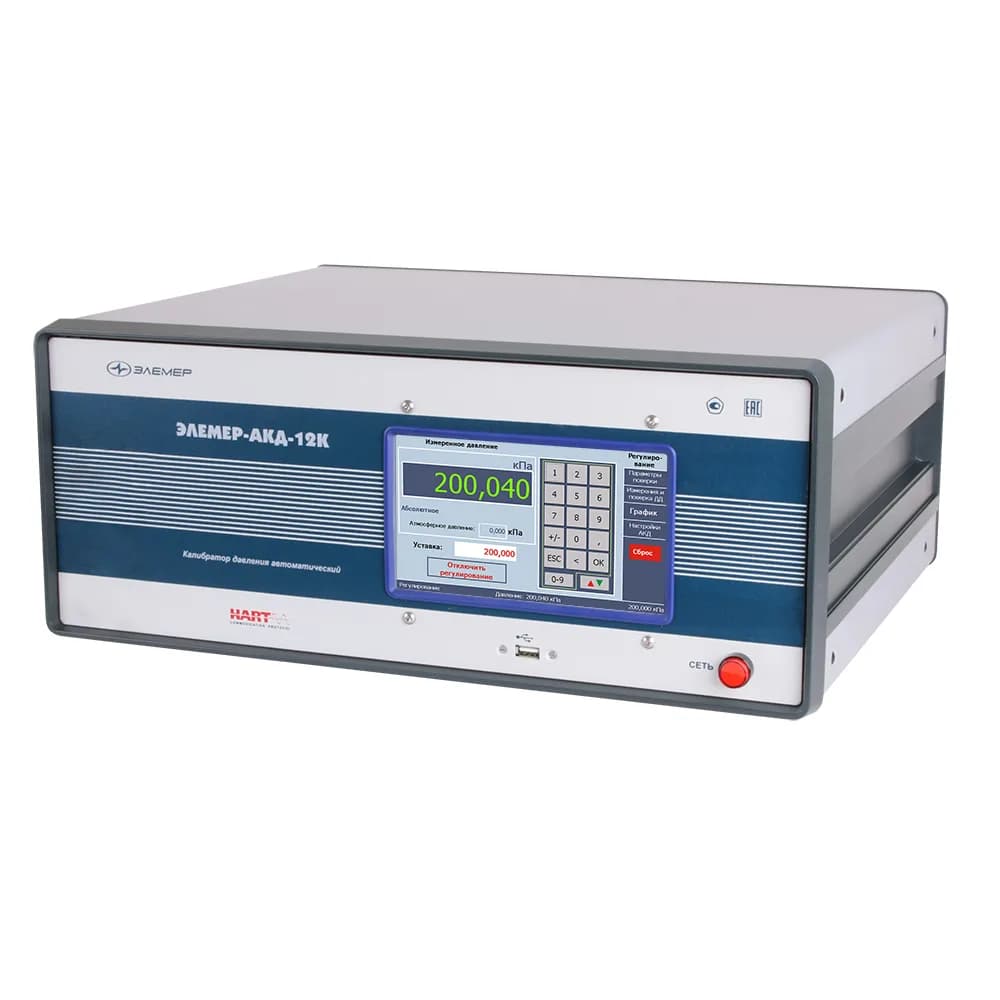
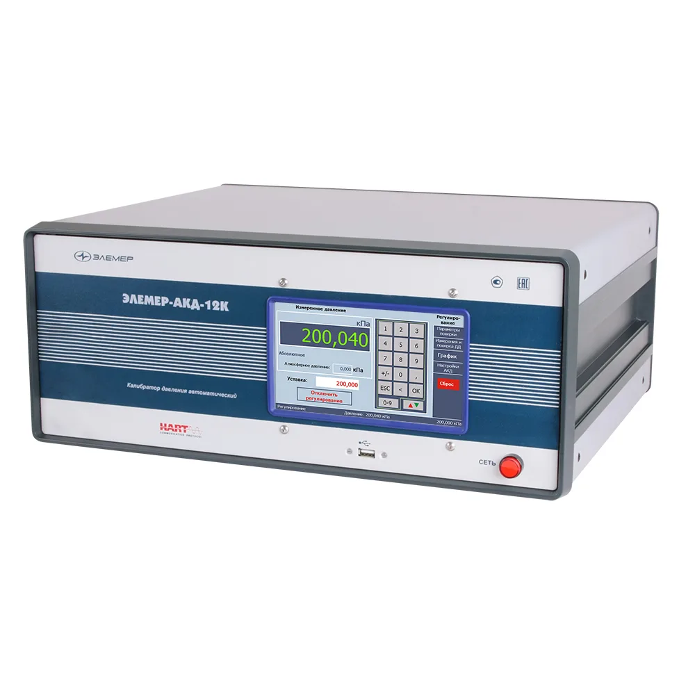
Калибраторы давления АКД, ПКД, КДМ
Калибраторы давления ЭЛЕМЕР-АКД, ПКД, КДМ — рабочие эталоны для поверки датчиков давления
Межповерочный интервал: от чего он реально зависит
Межповерочный интервал (МПИ) часто воспринимают как фиксированное число из паспорта прибора. На практике это отправная точка, которую нужно корректировать под реальные условия эксплуатации — иначе дефект измерительного канала обнаруживается по факту сбоя в АСУ ТП, а не по графику плановой поверки.
| Условия эксплуатации | Типичный МПИ | Комментарий |
|---|---|---|
| Стабильный процесс, умеренные давление и температура | 12–24 месяца | Базовый интервал по паспорту производителя |
| Циклические нагрузки, частые пуски и остановы | 6–12 месяцев | Ускоренная усталость чувствительного элемента |
| Агрессивная среда, вибрация корпуса прибора, гидроудары | 3–6 месяцев, плюс внеплановый контроль после инцидента | Повышенный риск скачкообразного дрейфа |
| Приборы систем противоаварийной защиты и коммерческого учёта | По требованиям нормативной документации, обычно короче технологического | Обязательная поверка, интервал не пересматривается предприятием произвольно |
Сокращение интервала для приборов в тяжёлых условиях эксплуатации стоит дешевле, чем один пропущенный дрейф на контуре, влияющем на безопасность или коммерческий учёт.
Как выбрать эталонный калибратор давления
Выбор эталонного калибратора давления определяется четырьмя параметрами:
- Диапазон давлений парка приборов — калибратор должен перекрывать весь диапазон рабочих приборов предприятия, включая вакуумметрические и избыточные измерения.
- Вид измеряемого давления — избыточное, абсолютное или дифференциальное; для дифференциальных преобразователей нужен калибратор с раздельными портами и контролем статического давления.
- Тип задающего устройства — встроенный пневматический насос для низких давлений, ручной гидравлический насос или подключение внешнего пресса для высоких давлений.
- Класс точности и соотношение погрешностей — рассчитывается от допуска самого «грубого» прибора в парке, а не от среднего.
| Диапазон давления | Рекомендуемое эталонное средство | Типовая задача |
|---|---|---|
| Вакуум … 2,5 МПа | Портативный калибратор давления со встроенным пневмонасосом | Поверка датчиков избыточного давления, тягонапоромеров, датчиков перепада |
| До 40–60 МПа | Калибратор с ручным гидравлическим насосом или подключением грузопоршневого пресса | Поверка манометров и преобразователей высокого давления, гидросистем |
| Прецизионные измерения, 1 разряд | Эталонный преобразователь давления в связке с цифровым эталонным манометром | Метрологическая лаборатория, поверка рабочих эталонов 2-го разряда |
Для полевых условий критична функция измерения токовой петли 4–20 мА одновременно с заданием эталонного давления — это позволяет за один цикл проверить и метрологическую характеристику, и корректность настройки диапазона преобразователя.
Как выбрать эталонный термометр и термопреобразователь
Для температурных каналов ключевые параметры выбора — рабочий диапазон, тип чувствительного элемента и способ создания контрольной температуры.
- Сухоблочные калибраторы — компактный нагреваемый/охлаждаемый блок с гнёздами под датчик; используются в полевых условиях и в цехе, обеспечивают умеренную скорость выхода на температуру и точность, достаточную для большинства ТСП и термопар.
- Жидкостные термостаты (масляные, водяные бани) — более равномерное температурное поле, выше точность и стабильность, применяются в стационарной лаборатории.
- Ампулы для реализации реперных точек — фазовые переходы чистых веществ (тройная точка воды, точка плавления галлия, цинка, олова) дают наиболее точное и воспроизводимое опорное значение для лабораторий 1–2 разряда.
- Эталонные термопреобразователи сопротивления и эталонные термопары — переносят реализованную температуру на измерительный прибор с минимальной дополнительной погрешностью.
| Диапазон температур | Рекомендуемый эталон | Область применения |
|---|---|---|
| −50…+150 °C | Портативный калибратор температуры + эталонный ТСП | Полевая поверка ТСП/ТСМ и термопар без демонтажа с трубопровода |
| −196…+660 °C (реперные точки) | Ампулы реперных точек + эталонные термопреобразователи | Поверочная лаборатория 1–2 разряда, аттестация рабочих эталонов |
| 0…+1200 °C | Эталонные термопары, печь сравнения, цифровые эталонные термометры ТТСЭ | Поверка технологических термопар высокотемпературных процессов (печи, котлы) |
Отдельное внимание — глубине погружения датчика при калибровке: недостаточное погружение в сухоблочный калибратор — одна из самых частых причин систематической ошибки при поверке длинных термопреобразователей с большим временем термической реакции.
Портативный калибратор, стационарный поверочный стенд или автоматизированная установка
Формат поверочного оборудования выбирается по объёму парка приборов, требуемой точности и месту проведения работ — на объекте или в лаборатории.
| Формат | Где применяется | Преимущества | Ограничения |
|---|---|---|---|
| Портативный полевой калибратор давления/температуры | Поверка на месте установки датчика, без демонтажа из технологической линии | Мобильность, автономное питание, встроенный HART-коммуникатор | Точность и диапазон уже, чем у стационарного эталона; влияние условий окружающей среды |
| Стационарный поверочный стенд (грузопоршневые манометры, прецизионные термостаты) | Метрологическая лаборатория предприятия | Высокая точность, широкий диапазон, соответствие поверочной схеме | Нужно выделенное помещение со стабильными температурой и влажностью |
| Автоматизированная поверочная установка (например, поверочные установки Элемер ПУ) | Массовая поверка партий однотипных приборов — десятки датчиков за смену | Минимизация человеческого фактора, автоматическое формирование протоколов, высокая производительность | Существенные первоначальные вложения, окупается при большом однородном парке приборов |
Практика показывает разумную комбинацию: портативный калибратор — для оперативной проверки и первичной диагностики на объекте, стационарный стенд или автоматизированная установка — для плановой поверки демонтированных приборов и аттестации рабочих эталонов внутри лаборатории предприятия.
HART-конфигурирование интеллектуальных преобразователей при калибровке
Большинство современных преобразователей давления и температуры — интеллектуальные, с цифровым протоколом HART поверх аналогового токового сигнала 4–20 мА. Калибровка такого прибора состоит из двух связанных, но разных операций, которые нельзя подменять одна другой:
- Sensor trim (коррекция датчика) — подстройка внутренней цифровой характеристики преобразователя по эталонному давлению или температуре. Выполняется, когда цифровое значение на HART-коммуникаторе устойчиво отличается от заданного эталоном.
- Output trim / D/A trim (коррекция аналогового выхода) — подстройка соответствия между цифровым значением и уровнем токового сигнала 4–20 мА, проверяется прецизионным измерением тока при опорных точках 4 и 20 мА.
Типовая последовательность при калибровке смарт-преобразователя:
- задать на эталонном калибраторе давления или температуры контрольную точку (обычно 0%, 50%, 100% диапазона в обе стороны хода);
- считать через HART-коммуникатор цифровое значение и сравнить с эталонным;
- при отклонении, превышающем допуск, выполнить sensor trim;
- проверить и при необходимости скорректировать нижнюю (LRV) и верхнюю (URV) границы диапазона, демпфирование, привязку тега;
- завершить проверкой аналогового выхода 4–20 мА относительно измеренного эталонным миллиамперметром тока.
Портативные калибраторы с интегрированным HART-модемом позволяют выполнять весь цикл — от задания эталонного давления/температуры до записи скорректированных параметров в память преобразователя — без переноски отдельного коммуникатора и без демонтажа прибора с линии.
Почему дрейф калибровки подрывает данные предиктивного обслуживания
Программы вибродиагностики и общего мониторинга состояния оборудования принято рассматривать отдельно от метрологии КИП. Это ошибка. Система вибрационного мониторинга не измеряет причину дефекта напрямую — она сопоставляет тренд вибрации с технологическими параметрами: давлением на всасе насоса, температурой подшипникового узла, перепадом давления на фильтре, расходом через теплообменник. Если эти параметры измеряются продрейфовавшим датчиком, диагностическая логика получает искажённый контекст:
- завышенное давление на всасе насоса маскирует реальный запас до кавитации (NPSH), и рост виброактивности в области лопаточных частот интерпретируется как «нормальный режим», хотя насос уже кавитирует;
- заниженная температура подшипникового узла сдвигает уставку теплового аварийного сигнала, и тепловой дефект развивается без срабатывания защиты, хотя вибрационный тренд уже показывает рост общего уровня;
- дрейф нуля датчика перепада давления на фильтре или сепараторе искажает расчётный ресурс элемента, приводя либо к преждевременной замене исправного элемента, либо к пропуску момента забивки.
Иначе говоря, порог тревоги виброконтроля или тренд предиктивной аналитики достоверен ровно настолько, насколько достоверны данные, которые в него поступают от датчиков давления и температуры. Программа поверки и калибровки — не бюрократическая надстройка над системой мониторинга состояния, а метрологический фундамент, без которого выводы PdM-системы нельзя проверить объективно. Это особенно критично в нефтегазовой отрасли и энергетике, где отклонение технологического параметра одновременно является входом и в систему безопасности, и в систему диагностики.
Как построить программу поверки и калибровки на предприятии
- Инвентаризация парка КИП — разделить приборы на подлежащие обязательной поверке и подлежащие технической калибровке.
- Определение межповерочных интервалов (МПИ) — на основе рекомендаций производителя, условий эксплуатации и статистики отказов, а не только формальных норм.
- Подбор эталонного оборудования под фактические диапазоны парка — портативные калибраторы давления и температуры для полевых работ, эталонные преобразователи и термопреобразователи для лаборатории.
- Организация поверочного участка или лаборатории — либо аутсорс в аккредитованную организацию, либо создание собственного участка со стационарным стендом или автоматизированной установкой при большом парке однотипных приборов.
- Ведение графика и архива свидетельств/сертификатов — с привязкой к конкретному техпозиции, а не только к серийному номеру прибора на складе.
- Интеграция с системой ТОиР и предиктивного обслуживания — статус метрологической поверки датчика должен быть виден инженеру по надёжности рядом с трендом вибрации и температуры, чтобы отличить реальный дефект оборудования от дрейфа измерительного канала.
Единая точка входа по всей линейке эталонного и рабочего измерительного оборудования — измерительная техника Элемер и профиль производителя.
Частые вопросы инженера по КИП
Можно ли поверить датчик давления и термопреобразователь одним и тем же эталонным прибором?
Нет. Давление и температура — разные физические величины с разными эталонными средствами и разными поверочными схемами. Универсальные многофункциональные калибраторы могут задавать и то, и другое поочерёдно, но опорный элемент (пневмонасос и датчик давления против сухоблочного нагревателя и эталонного ТСП) внутри такого прибора остаётся раздельным.
Что выгоднее — купить собственное эталонное оборудование или отдавать поверку на аутсорс?
Зависит от объёма парка приборов и частоты поверки. При парке в десятки датчиков разумнее периодически привлекать аккредитованную лабораторию. При парке в сотни приборов и регулярных внеплановых проверках собственный портативный калибратор и стационарный стенд окупаются за счёт сокращения простоя оборудования, ожидающего очереди на поверку.
Сам эталонный прибор тоже нужно поверять?
Да. Эталонное средство измерения — такой же объект метрологического контроля, только с более высоким разрядом и, как правило, более длинным межповерочным интервалом при бережной эксплуатации. Калибратор давления или температуры, который не поверяется сам, перестаёт быть эталоном и превращается в источник неконтролируемой погрешности для всего парка приборов, которые им проверяют.
Нужен ли HART-коммуникатор, если на предприятии установлены только аналоговые датчики 4–20 мА?
Для чисто аналоговых преобразователей без цифрового протокола HART-функциональность калибратора не используется — достаточно точного измерения давления/температуры и тока. Но парк современных смарт-преобразователей на новых объектах почти всегда включает HART, поэтому калибратор с интегрированным HART-модемом остаётся универсальным выбором на перспективу, даже если сегодня он используется не на каждом приборе.
Как связаны выбор эталонного оборудования и данные системы вибромониторинга, если она измеряет только вибрацию?
Напрямую системы вибромониторинга и КИП давления/температуры независимы по каналам измерения, но не по выводам, которые из них делает инженер по надёжности. Диагностическое заключение почти всегда строится на сопоставлении вибрационного тренда с рабочей точкой оборудования — нагрузкой, давлением, температурой процесса. Если рабочая точка определена по некалиброванному датчику, диагност либо не увидит корреляцию, которая есть на самом деле, либо примет случайное совпадение за закономерность.
Вывод
Поверка и калибровка средств измерений — это не разовая формальность перед проверкой контролирующего органа, а постоянный процесс, который поддерживает достоверность каждого числа, поступающего в систему управления и систему диагностики. Разница между рабочим прибором и эталоном — не в бренде, а в запасе точности, который обязан быть кратно выше допуска поверяемого канала. Выбор эталонного калибратора давления, эталонного термометра и формата поверочных работ — портативного, стационарного или автоматизированного — определяется реальным диапазоном и объёмом парка приборов предприятия, а не универсальным решением.
Отдельно стоит подчеркнуть связь с предиктивным обслуживанием: тревога виброконтроля, тренд износа подшипника или расчёт остаточного ресурса узла опираются на технологические параметры, снятые датчиками давления и температуры. Без действующей программы поверки и калибровки этих датчиков любая PdM-система работает на данных с неизвестной степенью достоверности. Метрологическая дисциплина — это основание, на котором строится вся остальная диагностика состояния оборудования.
Оборудование в статье
Цены и сроки поставки в Казахстан KEG TRK сообщает по запросу. Подготовим коммерческое предложение под вашу задачу.
Калибраторы давления АКД, ПКД, КДМ
Калибраторы давления ЭЛЕМЕР-АКД, ПКД, КДМ — рабочие эталоны для поверки датчиков давления
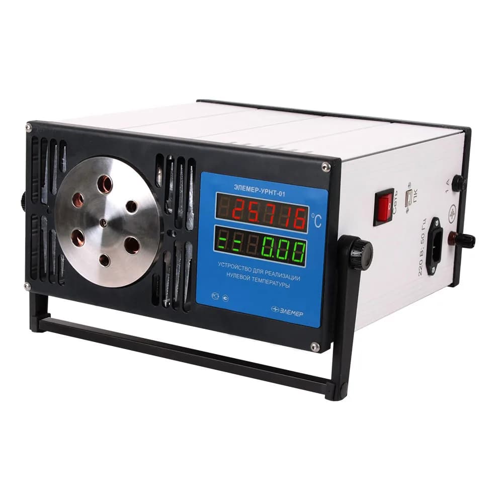
Калибратор температуры ЭЛЕМЕР-КТ-УРНТ-01 (точка 0 °C)
Погружной калибратор точки 0 °C ЭЛЕМЕР-КТ-УРНТ-01 — замена термостата лёд-вода
Также в статье: Эталонный преобразователь давления ПДЭ-040, Эталонные термометры ЭТС, ПТСВ, ППО
Читайте также
10.10.2026
Что такое вибродиагностика оборудования и с чего начать
Вибродиагностика — контроль состояния машин по вибрации опор. Что измеряют, чем маршрутный контроль отличается от онлайн-мониторинга, какие дефекты видно в спектре и как начать программу.
10.10.2026
Диагностика электродвигателя: какие методы что показывают
Вибрация, ультразвук, термография, анализ тока (MCSA/ESA), анализ цепи двигателя (MCA), мегаомметр и анализ масла: какие дефекты видит каждый метод, где его предел и как их сочетать.
10.10.2026
Как проверить подшипник электродвигателя без разборки: 5 способов
Пять способов проверить подшипник на работающем двигателе: слух и стетоскоп, пирометр, вибрация, ультразвук и анализ тока. Что видит каждый метод, где его предел и в каком порядке их применять.