
Vacuum suction cup will not hold: causes and air ingress inspection
Separate hose and fitting leaks, cup wear, workpiece porosity and insufficient vacuum generation before changing the operating settings.
If a vacuum gripper stops holding a workpiece, increasing the vacuum setpoint does not replace diagnosis. The fault may be in the circuit, the cup or a changed workpiece. Identify what changed first: material, surface, cups, hoses or cycle conditions.
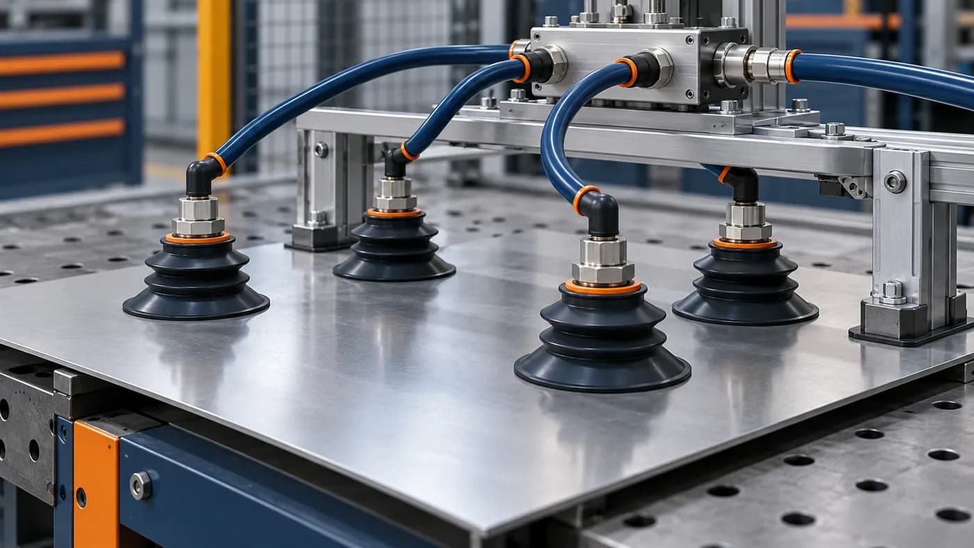
The cover is an illustration of a generic gripper on a supported workpiece, not a photograph of a particular model or client site.
Match the symptom to the inspection
| Symptom | First inspection focus |
|---|---|
| Fault started after a hose change | Connections, kinks, internal diameter and line length |
| Only one cup loses vacuum | Sealing lip, contact, contamination and that branch's fitting |
| A nonporous reference surface works but the new workpiece does not | Porosity, roughness, coating and cup suitability |
| All cups evacuate slowly | Generator, filter, valves and flow restrictions |
| Vacuum is established but the part slips during the cycle | Gripper arrangement, contact, load direction and motion |
Vacuum condition and holding ability are related but distinct checks. A reading at the generator may not describe conditions at a remote cup.
Prepare a comparable test
Use a supported workpiece and the manufacturer's service mode. Do not use a suspended load as a test fixture. Record workpiece type, surface condition, generator mode, time to setpoint and pressure measurement location.
Compare sound and suspect branches under the same conditions. Isolate circuit sections only where the procedure permits it. Record disconnected consumers: isolation changes the system, so a different operating mode must not be mistaken for a successful repair.
Equipment covered in this article
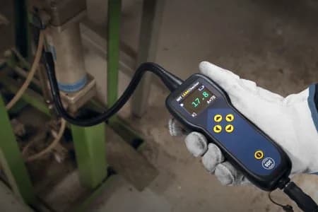
LEAKChecker - Compressed-Air Leak Detector
Specialised detector for fast detection of compressed-air and gas leaks
When airborne ultrasound helps
Under a pressure differential, an accessible hose, fitting or seal defect may produce a distinguishable ultrasonic signal. A directional airborne sensor supports localization. See the vacuum system inspection route.
Ultrasound does not select cup material or verify load capacity. No signal does not prove tightness; consider access, background noise and flow. LEAKChecker or SDT340 with an airborne sensor can support source localization.
Gather cup selection data
Provide workpiece material and shape, surface condition, temperature, oil or moisture, dimensions and mass, motion direction, cycle parameters and the available vacuum system. Lip material, shape and effective contact area must suit the task. Nominal diameter alone does not define an allowable load.
Select and accept the gripper using manufacturer documentation and testing in the required operating mode, including motion. Replacing a worn lip may remove air ingress but cannot compensate for an unsuitable surface or arrangement.
Verify the repair
Record the leak location, replaced component, before-and-after conditions and repeat cycle results. For KEG TRK, attach a circuit diagram and fitting photos to help select an inspection method by task.
Related: air and gas leak detection, compressed air inspection route.
Sources
Schmalz suction cup design, cup materials, FQE troubleshooting manual and SDT airborne sensor documentation. This article outlines an initial inspection approach, not model-specific operating parameters.
Equipment in this article
KEG TRK quotes prices and delivery times to Kazakhstan on request. We will prepare a commercial offer for your application.
LEAKChecker - Compressed-Air Leak Detector
Specialised detector for fast detection of compressed-air and gas leaks
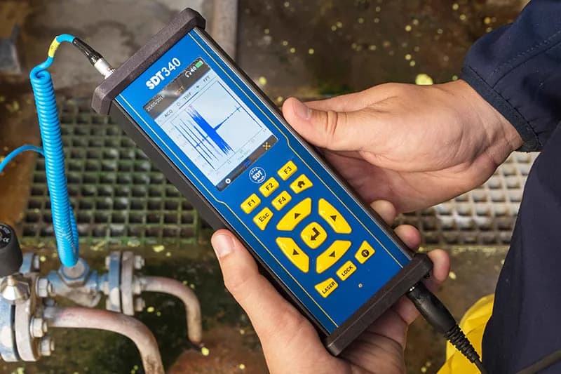
SDT340 - Advanced Ultrasound Detector
The most advanced ultrasound detector for collecting, analysing and trending data
Read also
10/6/2026
Compressed air leak detection: inspection route and repair verification
Inspect the air network, register defects, assign repairs and verify the result: a practical route for compressor stations and production areas.
10/6/2026
Finding air ingress in a vacuum system: inspection route and verification
Vacuum fails to reach its setpoint or drops under load: inspect joints, hoses, valves and seals, choose a method and verify the repair.
7/17/2026
Leaks in heat exchangers and condensers: the ultrasonic detection method
Tube bundles in CHP and metals condensers and heat exchangers develop micro-leaks long before a visible vacuum drop. How the SDT340 and the compressed-air method pinpoint the faulty tube without a full teardown.