

How to Find Compressed Air Leaks in a Plant: 5 Methods
Compressed air leaks are found in two steps: first estimate the losses from how the compressor runs, then locate the points with an ultrasonic detector or an acoustic camera. Five methods and where each one works.
Compressed air leaks are found in two steps. First, estimate whether there are losses and how large they are, from how the compressor runs while consumers are shut down. Then locate the actual points with an ultrasonic detector or an acoustic camera, and confirm them with soapy water on accessible joints. Below are five methods, what they can do and their limits.
How to tell that there are leaks
The simplest sign: the compressor keeps reloading when nobody is working (at night, at weekends, during breaks). Nobody is using air at that time, so it is escaping through leaks.
For compressors with load/unload control, the leak share can be estimated without instruments. Turn off the consumers, start the compressor and time several cycles:
leakage (%) = T × 100 / (T + t)
where T is the on-load time and t is the off-load time.
Example: the compressor loads for 4 minutes and runs unloaded for 12 minutes. Leakage = 4 × 100 / (4 + 12) = 25%, so a quarter of its output goes to leaks.
The method comes from U.S. Department of Energy (DOE) guidance. If the compressor also has a separate full-stop mode, check which time counts as t: the original method refers to off-load time.
For other control types, leakage is estimated from the pressure drop in the receiver. Bring the network to working pressure P1, stop the supply and time how long (T) it takes to fall to roughly half the working pressure, P2. Then:
leakage (m³/min free air) ≈ V × (P1 − P2) / (T × 1.013) × 1.25
where V is the volume of receivers, mains and piping in m³, P1 and P2 are gauge pressures in bar, T is the time in minutes, and 1.25 corrects for leakage falling as the pressure drops.
Both estimates show the size of the losses but not where they are. DOE recommends repeating them quarterly as part of a leak detection and repair programme. To find the locations, use one of the methods below.
5 ways to find a leak
| Method | What it gives | Where it works | Limits |
|---|---|---|---|
| Compressor-based estimate | Loss as a percentage | The whole network at once | Does not show where the leak is |
| By ear | Large leaks | Quiet areas, stopped production | In a running plant only the strongest are audible |
| Soapy water or foam | Confirmation of a specific point | Accessible joints | Slow, awkward at height, not allowed everywhere |
| Ultrasonic detector | Leak location on a live network | Any plant, including noisy ones | You have to walk the route and check every joint |
| Acoustic camera | Source on screen, area overview | Large areas, overhead pipework, pipe racks | Costs more than a detector; the point is confirmed close up |
Why ultrasound works in a noisy plant
Air escaping through a gap under pressure creates turbulence, and turbulence produces ultrasound. An ultrasonic detector picks up this signal and converts it into audible sound in the headphones. Plant noise is mostly in the audible range, while ultrasound fades quickly with distance, so following the rising signal leads straight to the source. More on the method in Ultrasound Inspection: A Beginner's Guide.
When you need an acoustic camera
A camera collects ultrasound with a microphone array and overlays the source on a video image. It saves time where a detector would mean checking every joint from a ladder: overhead pipework, pipe racks, large halls. A model comparison is in SonaVu or Crysound: which acoustic camera to choose.
Equipment covered in this article
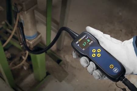
LEAKChecker - Compressed-Air Leak Detector
Specialised detector for fast detection of compressed-air and gas leaks
Where to look first
- threaded and quick-disconnect fittings;
- hoses and their end fittings;
- air preparation units: filters, regulators, lubricators;
- valves, directional valves and pneumatic cylinders (rod seals);
- pressure regulators and shut-off valves;
- drains and condensate traps stuck open;
- pipe joints with poor or badly applied thread sealant;
- capped and unused branches still under pressure: isolate them with a valve.
Survey order
- Estimate the leak share from the compressor so you have a baseline for after the repairs.
- Walk the network from the compressor room to the consumers: mains, branches, points of use.
- Tag and photograph every leak found, and record the location, equipment and signal strength.
- Repair, starting with the strongest leaks.
- Repeat the compressor estimate: the difference shows the effect of the repairs.
A detailed procedure with a log and repair follow-up is in Compressed air leak detection: survey route.
What leaks cost
According to DOE, plants without regular maintenance typically leak about 20% of compressor output, sometimes 20–30%. Regular detection and repair keeps leakage below 10%. Network pressure is another lever: the lower it is, the less air escapes through the same gap, so keeping pressure at the lowest level the consumers need pays off. The cost depends on compressor power, operating hours and the electricity tariff; you can work it out in the compressed air leak calculator.
Which instrument to choose
- A one-off survey of a small network: the dedicated LEAKChecker detector. Switch it on and walk the route; it needs almost no training.
- A regular programme with reports and history: SDT270 or SDT340 detectors with LEAKReporter software.
- Large areas, height, hazardous zones: SonaVu acoustic cameras, including the ATEX version.
KEG TRK supplies these instruments in Kazakhstan and helps choose them for the task. Price on request.
Sources
- U.S. Department of Energy, Compressed Air Challenge. Compressed Air System Leaks (Fact Sheet 7).
Frequently asked questions
Equipment in this article
KEG TRK quotes prices and delivery times to Kazakhstan on request. We will prepare a commercial offer for your application.
LEAKChecker - Compressed-Air Leak Detector
Specialised detector for fast detection of compressed-air and gas leaks
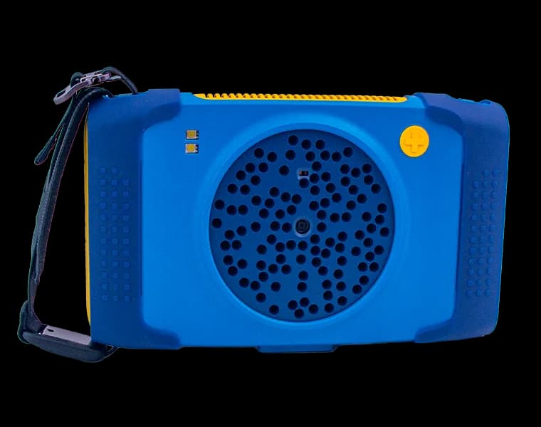
SDT SonaVu+ - Next-Generation Acoustic Camera
SonaVu+ acoustic camera with 112 sensors, a built-in display and a detection range of up to 200 metres — for leak detection, electrical inspection and mechanical-defect…
Read also
10/10/2026
Electric Motor Vibration Limits per ISO 10816-3: Zone A–D Table
Motors above 15 kW are assessed by RMS vibration velocity in the 10–1000 Hz band. For 15–300 kW machines on rigid foundations the zone boundaries are 1.4 / 2.8 / 4.5 mm/s. Full tables and how to apply them.
8/24/2026
Oil Analysis and Tribology: The Third Pillar of Predictive Monitoring
Oil analysis reveals wear, contamination and lubricant degradation long before ultrasound hears it or vibration analysis sees it. We examine the method as the third pillar of condition monitoring.
6/30/2026
Launch an SDT ultrasound route in 90 days: step-by-step plan
From SDT340 purchase to first management report: asset register, baseline, LUBExpert, leaks and CMMS integration.