
Electric Motor Vibration Limits per ISO 10816-3: Zone A–D Table
Motors above 15 kW are assessed by RMS vibration velocity in the 10–1000 Hz band. For 15–300 kW machines on rigid foundations the zone boundaries are 1.4 / 2.8 / 4.5 mm/s. Full tables and how to apply them.
Electric motors above 15 kW are assessed under ISO 10816-3: measure the RMS vibration velocity on the bearing housings in the 10–1000 Hz band and compare it with the boundaries of zones A, B, C and D. For 15–300 kW motors on rigid foundations the boundaries are 1.4 / 2.8 / 4.5 mm/s; for motors above 300 kW they are 2.3 / 4.5 / 7.1 mm/s. The full tables and how to apply them are below.
Which group your motor belongs to
ISO 10816-3:1998 (adopted in Russia as GOST R ISO 10816-3-99) covers machines above 15 kW running at 120 to 15,000 r/min: electric motors, pumps (except reciprocating), fans, rotary compressors and generators. For electrical machines the group is set by power or by shaft height H:
| Group | Power | Shaft height | Typical bearings |
|---|---|---|---|
| 1 | above 300 kW (up to 50 MW) | above 315 mm | sleeve |
| 2 | 15–300 kW | 160–315 mm | rolling element, speed above 600 r/min |
Shaft height H is the distance from the shaft centreline to the machine's base plane. For vertical machines it is determined as if the machine were mounted horizontally.
Rigid or flexible support
A support is rigid in the measurement direction if the first natural frequency of the machine and support system is at least 25% higher than the main excitation frequency, usually the rotor running speed. All other supports are flexible. Large and medium motors with low running speeds are usually on rigid supports; turbo-generators, large compressors and vertical machines are more often on flexible ones. The same support can be rigid vertically and flexible horizontally; each direction is then assessed against its own table.
Equipment covered in this article
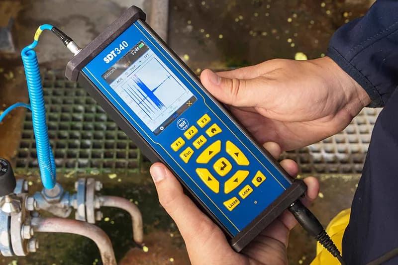
SDT340 - Advanced Ultrasound Detector
The most advanced ultrasound detector for collecting, analysing and trending data
Zone boundary tables
Values are RMS in the 10–1000 Hz broadband (2–1000 Hz for machines below 600 r/min).
Group 1: machines above 300 kW, electrical machines with shaft height above 315 mm (table A.1):
| Support | Boundary | Displacement, µm | Velocity, mm/s |
|---|---|---|---|
| Rigid | A/B | 29 | 2.3 |
| B/C | 57 | 4.5 | |
| C/D | 90 | 7.1 | |
| Flexible | A/B | 45 | 3.5 |
| B/C | 90 | 7.1 | |
| C/D | 140 | 11.0 |
Group 2: machines 15–300 kW, electrical machines with shaft height 160–315 mm (table A.2):
| Support | Boundary | Displacement, µm | Velocity, mm/s |
|---|---|---|---|
| Rigid | A/B | 22 | 1.4 |
| B/C | 45 | 2.8 | |
| C/D | 71 | 4.5 | |
| Flexible | A/B | 37 | 2.3 |
| B/C | 71 | 4.5 | |
| C/D | 113 | 7.1 |
The standard has separate tables for centrifugal pumps above 15 kW: group 3 (separate driver) uses the same velocity boundaries as group 1, and group 4 (integral driver) the same as group 2.
What the zones mean
| Zone | Condition |
|---|---|
| A | Vibration of newly commissioned machines |
| B | Acceptable for unrestricted long-term operation |
| C | Unsatisfactory for long-term continuous operation; may run for a limited time until repair |
| D | Vibration may cause serious damage to the machine |
The standard notes that these boundaries are not intended as acceptance criteria for new machines; acceptance terms are agreed between manufacturer and customer.
How to measure correctly
- Run the motor in steady state: rated speed and load, bearings at operating temperature.
- Mount the sensor on the cap or housing of each bearing, in two orthogonal radial directions (usually horizontal and vertical for a horizontal machine). Axial readings are taken on periodic rounds.
- Assess against the highest value measured across all points and directions.
- If vibration is above the limit, check the background: measure the machine while it is stopped. If that exceeds 25% of the running vibration, the result has to be corrected for nearby equipment.
- The instrument must read RMS. If it reads peak and the signal is close to sinusoidal, divide the peak by √2 (about 1.41).
Example
A pump motor: 75 kW, shaft height 225 mm, on a massive frame, so group 2 with a rigid support. The highest reading is 3.2 mm/s. That is zone C (2.8–4.5 mm/s): the motor can run for a limited time and a repair needs to be planned. To find out what to repair (unbalance, misalignment, a bearing or looseness) you need spectrum analysis; see How to read an FFT spectrum.
Alarm and trip
- Change in vibration. An increase or decrease in broadband vibration of more than 25% of the zone B upper limit is significant even if zone C has not been reached. Investigate the cause.
- ALARM. Recommended above the machine's baseline by 25% of the zone B upper limit, and not above 1.25 times that limit.
- TRIP. Usually within zone C or D, but not above 1.25 times the zone C upper limit.
Limits of the standard
- It does not cover motors up to 15 kW, submersible motor pumps, reciprocating machines, steam turbine sets above 0.5 MW, or machines at hydro and pumping power stations.
- It assesses only overall broadband vibration; it is not intended for diagnosing gears or rolling element bearings.
- ISO 10816-3 has been replaced internationally by the ISO 20816 series. Check which edition applies at your site.
What to measure with
For periodic rounds, the SDT340 ultrasonic detector has a 10 Hz – 10 kHz vibration channel and measures bearing vibration and ultrasound together. For continuous monitoring without cabling, Wi-care wireless sensors; more in Wireless vibration monitoring. KEG TRK supplies the instruments in Kazakhstan and helps set up a monitoring programme. Price on request.
Sources
- ISO 10816-3:1998 / GOST R ISO 10816-3-99, "Mechanical vibration. Evaluation of machine vibration by measurements on non-rotating parts. Part 3: Industrial machines with nominal power above 15 kW and nominal speeds between 120 r/min and 15 000 r/min", clauses 1, 3–5 and annex A.
Frequently asked questions
Equipment in this article
KEG TRK quotes prices and delivery times to Kazakhstan on request. We will prepare a commercial offer for your application.
SDT340 - Advanced Ultrasound Detector
The most advanced ultrasound detector for collecting, analysing and trending data
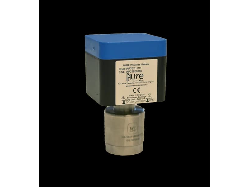
I-care Wi-care 240 — continuous monitoring module
Wi-care 200 series module for continuous monitoring: 4 dynamic vibration channels with temperature, 2 Smart Tach speed inputs up to 20,000 RPM, any IEPE accelerometer…
Read also
8/24/2026
Oil Analysis and Tribology: The Third Pillar of Predictive Monitoring
Oil analysis reveals wear, contamination and lubricant degradation long before ultrasound hears it or vibration analysis sees it. We examine the method as the third pillar of condition monitoring.
6/30/2026
Integrated PdM on One Site: Artesis + Bently Nevada + SDT
Three KEG TRK pillars on one plant: Bently vibration on turbo-machinery, SDT ultrasound on routes, Artesis ESA on motors and generators — zone matrix, workflow and architecture.
6/30/2026
How to improve plant reliability in 5 steps: SDT + Artesis
No big-bang PdM: asset register, SDT quick wins, AMT Pro route, e-MCM on chronic assets, KPI governance.