
Finding air ingress in a vacuum system: inspection route and verification
Vacuum fails to reach its setpoint or drops under load: inspect joints, hoses, valves and seals, choose a method and verify the repair.
Slow evacuation does not prove a leak. First separate pump performance from possible air ingress. Process load, a blocked filter, pump condition and gas released by the product can also affect pressure.
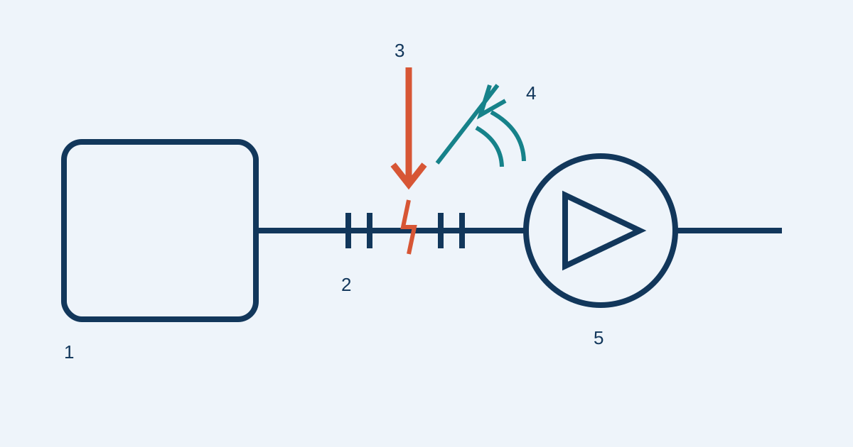
The diagram shows 1 a vacuum vessel, 2 pipe joints, 3 atmospheric air entering through a defect, 4 a directional airborne ultrasonic sensor, and 5 the vacuum pump. It illustrates the principle; it is not an installation drawing.
Start with the symptom
| Observation | Inspection focus |
|---|---|
| Vacuum worsened after maintenance | Flange assembly, gaskets, valve positions |
| Vacuum drops when one branch is connected | Hoses, joints and consumers on that branch |
| Evacuation is slow with the section isolated | Pump, filter, pressure measurement and gas load |
| Pressure rises after isolation | Boundary tightness, gas release and evaporation |
Record the pressure unit and whether it is absolute pressure or gauge vacuum. Compare results under the same process load.
Inspection route
- Record pressure, operating mode, connected branches and evacuation time.
- Isolate a section only under an approved procedure compatible with the process and pump operating limits.
- Inspect accessible flanges, threaded fittings, flexible hoses, valve stems, filter covers and seals. Mark recent maintenance locations.
- With a pressure differential present, scan with an airborne ultrasonic sensor. Start with a broad scan and then approach suspect joints; keep settings consistent for comparisons.
- Check from several directions. Nearby pneumatics and reflections can mislead localization. A signal peak alone is not proof of a defect.
- Record a point number, photograph, conditions and findings. After repair, repeat the inspection and check vacuum recovery under the same conditions.
Equipment covered in this article
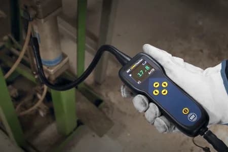
LEAKChecker - Compressed-Air Leak Detector
Specialised detector for fast detection of compressed-air and gas leaks
Select a method by the required result
Airborne ultrasound can locate accessible turbulent flow under a pressure differential. A directional sensor suits joint-by-joint inspection. An acoustic camera can support a broad survey; distance, background noise and sensitivity requirements determine suitability.
Pressure-rise testing measures change in an isolated volume but does not locate the source. Gas release and temperature changes also affect the result.
Tracer testing may be needed when the required tightness or defect size exceeds acoustic detection capability. Select the tracer, instrument, procedure and acceptance criterion for the installation.
No ultrasonic signal does not prove tightness. Small flow, limited access, background noise and operating conditions can conceal a defect. A contact sensor for bearings does not replace an airborne leak sensor.
Prepare an inspection request
Provide the equipment, medium, pressure and units, access conditions, symptoms, isolation options and required result: localization or verification against a tightness limit. Attach photographs and a diagram. Contact KEG TRK to discuss the method.
Consider LEAKChecker for route inspections or SDT340 with an appropriate airborne sensor for a broader inspection program.
Related reading: leak detection methods, pump suction and dry running, heat exchanger and condenser leaks.
Sources and scope
SDT airborne sensors and the DOE compressed air sourcebook provide background on acoustic leak detection. The route above is a practical inspection structure, not an acceptance standard or a replacement for the installation procedure.
Equipment in this article
KEG TRK quotes prices and delivery times to Kazakhstan on request. We will prepare a commercial offer for your application.
LEAKChecker - Compressed-Air Leak Detector
Specialised detector for fast detection of compressed-air and gas leaks
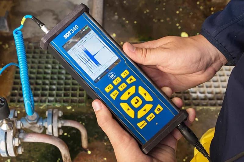
SDT340 - Advanced Ultrasound Detector
The most advanced ultrasound detector for collecting, analysing and trending data
Read also
10/6/2026
Compressed air leak detection: inspection route and repair verification
Inspect the air network, register defects, assign repairs and verify the result: a practical route for compressor stations and production areas.
10/6/2026
Vacuum suction cup will not hold: causes and air ingress inspection
Separate hose and fitting leaks, cup wear, workpiece porosity and insufficient vacuum generation before changing the operating settings.
7/17/2026
Leaks in heat exchangers and condensers: the ultrasonic detection method
Tube bundles in CHP and metals condensers and heat exchangers develop micro-leaks long before a visible vacuum drop. How the SDT340 and the compressed-air method pinpoint the faulty tube without a full teardown.