
Eddy current testing: how it works and where it is used
An AC coil induces eddy currents in metal; a flaw changes them and the coil impedance. The method finds surface cracks, inspects tubes, measures conductivity and coatings. Conductive materials only.
In this article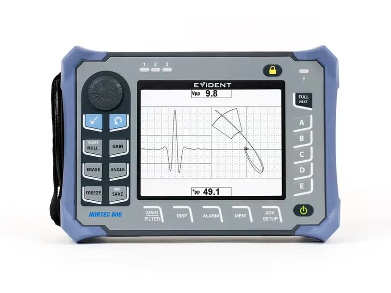
Prepared by the KEG TRK team · How we prepare our content
Eddy current testing is based on electromagnetic induction: a coil carrying alternating current induces eddy currents in metal, and a crack, wall thinning or a change in conductivity alters those currents and the coil impedance. The instrument shows the change on the impedance plane. The method finds surface cracks, inspects heat exchanger tubes and measures conductivity and coating thickness. It works only on conductive materials.
Below: how the method works, how to read the impedance plane, how frequency sets the inspection depth, which probes exist and where the method does not work. Where eddy current fits among other methods is shown in "Non-destructive testing methods".
Principle: what happens in the metal
- Alternating current flows through the probe coil and creates an alternating magnetic field around it.
- Near a conductive part, this field induces closed circular currents in it, called eddy currents.
- The eddy currents create their own field that opposes the coil's field. The energy to create them is taken from the coil, so its resistance increases and its inductive reactance changes.
- A crack interrupts the path of the eddy currents and weakens them. The coil impedance changes and the instrument records it.
No contact with the part and no couplant are needed, and the result is immediate. Evident and the NDT Resource Center list among the method's advantages sensitivity to small cracks, minimal surface preparation and portable equipment.
Do not confuse this with eddy current displacement probes in vibration monitoring systems: they measure the gap to a shaft rather than look for flaws. That application is covered in "3300 XL eddy current sensors on large fans".
The impedance plane: how to read the signal
Coil impedance Z is made up of resistance R and inductive reactance XL. They are 90° out of phase, so they add as vectors:
|Z| = √(R² + XL²), tan φ = XL / R
On an eddy current instrument screen R is plotted horizontally and XL vertically. Each change under the probe moves the point in its own direction:
| What happens | How the signal changes |
|---|---|
| Probe moved from air onto aluminium (non-magnetic conductor) | R increases, XL decreases |
| Crack in the aluminium under the probe | Fewer eddy currents: R goes back down, XL goes up |
| Probe placed on steel (ferromagnetic) | R increases and XL also increases: the steel's permeability concentrates the coil field |
| Probe-to-part gap changes (lift-off) | The point moves along its lift-off line; in Evident's typical setup, after nulling on the part, lifting the probe moves the signal horizontally to the left |
The main goal of setup is to separate the flaw signal from the lift-off signal by angle. The instrument is calibrated on a reference standard, and settings are not changed during the inspection.
Equipment covered in this article
Olympus NORTEC 600 — eddy current flaw detector
Portable Olympus (Evident) eddy current flaw detector: 10 Hz–12 MHz, four versions (600, 600C, 600S, 600D), conductivity 0.9–110 % IACS and non-conductive coating…
Frequency and depth of penetration
Eddy currents are strongest at the surface and decrease exponentially with depth (the skin effect). The standard depth of penetration δ is the depth at which current density falls to 1/e, about 37% of the surface value. At 2δ, 13.5% remains; at 3δ, only 5%.
The formula from the NDT Resource Center:
δ ≈ 1 / √(π·f·μ·σ) (δ in metres, f in Hz, μ in H/m, σ in S/m)
In working units:
δ (mm) ≈ 661 / √(f · μr · σ), where f is in Hz, μr is relative magnetic permeability and σ is conductivity in % IACS
Depth decreases as frequency, conductivity and permeability increase. A calculation with this formula for three materials (conductivity from NDT Resource Center tables):
| Frequency | Copper, 100% IACS | Aluminium 7075-T76, 38.5% IACS | Stainless steel 304, 2.5% IACS, μr 1.05 |
|---|---|---|---|
| 1 kHz | 2.1 mm | 3.4 mm | 12.9 mm |
| 10 kHz | 0.66 mm | 1.07 mm | 4.1 mm |
| 100 kHz | 0.21 mm | 0.34 mm | 1.3 mm |
| 1 MHz | 0.07 mm | 0.11 mm | 0.41 mm |
An example from the same reference: for 304 stainless steel at 50 kHz, δ ≈ 1.8 mm. The reverse problem: to get δ = 2 mm in 7075-T76 aluminium you need a frequency of about 2.8 kHz (f ≈ 436,921 / (δ²·μr·σ)).
The table does not apply to carbon steel: its permeability is high and variable, so eddy currents stay at the very surface. Evident states directly that on carbon steel the method detects surface defects only.
How to choose the frequency for the task
- Surface cracks: as high a frequency as possible, for resolution and sensitivity.
- Subsurface flaws: lower the frequency for depth, at the cost of sensitivity. Ferromagnetic and highly conductive materials need an even lower frequency.
- Flaw at a known depth: the NDT Resource Center recommends a frequency at which δ roughly equals the flaw depth. Then the flaw and lift-off signals separate well in phase.
- Thin sheet thickness: choose the frequency so that δ is 25% greater than the thickness (t = 0.8δ). The thickness-change and lift-off signals then separate by about 90°.
- Non-conductive coating thickness: the highest practical frequency, to reduce the influence of the base metal.
Phase lag and flaw depth
Current at depth x lags in phase behind the surface current: θ = x / δ radians, or θ = (x / δ) × 57.3 degrees. On the impedance plane the angle between the lift-off and flaw signals is about twice θ. If δ is 1.25 times the flaw depth, θ ≈ 45° and the signals separate by about 90°. This angle is used to estimate how deep a flaw lies.
Probe types
Probes are classified by mode of operation (how the coils are wired) and by configuration.
| Mode | Design | Used for |
|---|---|---|
| Absolute | One test coil | Cracks, conductivity, lift-off, thickness. Sensitive to conductivity, permeability, gap and temperature |
| Differential | Two coils wound in opposition | Very sensitive to local flaws, little response to gradual changes in dimensions and temperature. A long flaw shows only at its ends |
| Reflection (driver/pickup) | Separate excitation and pickup coils | Each coil is optimised separately; a small pickup coil sees small flaws |
| Hybrid | A combination of designs | Special tasks |
| Configuration | Application |
|---|---|
| Surface (pancake) | Cracks perpendicular to the surface; wide coils for large areas and conductivity |
| Pencil | Small coil in a slender housing for restricted spaces and bores |
| Bolt hole | Rotated inside the hole by a scanner |
| ID (bobbin) | Inserted into a tube, inspects the full circumference from inside |
| OD (encircling) | Encircles a tube or bar, inspects from outside |
A larger coil covers more volume and penetrates deeper; a smaller coil is better at finding small flaws.
Where it is used
Surface cracks
The method works well when the likely flaw type, location and orientation are known. The procedure with a surface probe according to the NDT Resource Center:
- Select the instrument, probe and a frequency for the required depth.
- Set up the instrument on a reference standard of the same material with artificial flaws (saw cuts, holes) so the flaw signal is easy to recognise.
- Place the probe on the part and null the instrument.
- Scan the surface with full coverage, keeping the probe orientation constant: probe wobble distorts the signal.
- Watch for a local change in impedance as the probe passes over a discontinuity.
Typical tasks from Evident materials: cracks in machined parts and metal stock, around fasteners in aircraft structures, in bolt holes, and surface inspection of welds together with ultrasonics for the volume.
Heat exchanger and steam generator tubes
Eddy current testing looks for corrosion, erosion, cracking and thinning in tubes, of which a heat exchanger has thousands. A typical technique is to pull a differential bobbin probe through the tube. While the wall is intact there is no signal. Over thinning, a loop appears on the impedance plane from one coil and then a second loop from the other. The depth of outside corrosion is estimated from the phase lag and its extent from the signal size. An absolute probe responds much more strongly to dings and magnetite build-up on the outside of the tube.
Conductivity and heat treatment
A metal's electrical conductivity depends on its chemical composition and structural state. It is used to sort alloys, verify heat treatment and detect heat damage. Conditions:
- the method applies to non-magnetic materials: in ferromagnetic ones the permeability effect cannot be separated from conductivity;
- the part must be at least 3δ thick, otherwise thickness affects the result;
- conductivity depends on temperature, so measure at a constant temperature or apply a correction.
Coating thickness
The thickness of non-conductive coatings (such as paint) on a conductive base is measured from the lift-off signal: each thickness corresponds to its own point position, and alarms can be set for coatings that are too thick or too thin.
Limitations of the method
- Conductive materials only.
- Limited depth: the method is for surface and near-surface flaws; the volume is better inspected ultrasonically. How pipe wall thickness is measured with ultrasound is shown in "How to measure pipe wall thickness with ultrasound".
- Delaminations parallel to the coil winding and the scan direction are not detected.
- Surface roughness and permeability variations cause noise.
- The probe needs access to the surface, and reference standards must match the part in material and shape. Calibration is repeated at the start of every inspection.
- Operator skill and training requirements are higher than for many other methods.
Which instrument to choose
Olympus (Evident) NORTEC 600 is a portable eddy current flaw detector with a frequency range of 10 Hz to 12 MHz. According to Evident:
| Parameter | NORTEC 600 |
|---|---|
| Versions | N600 (basic), N600C (conductivity), N600S (rotating scanners), N600D (dual frequency) |
| Frequency | 10 Hz - 12 MHz |
| Gain | 0-100 dB in 0.1 or 1 dB steps |
| Conductivity (C, S, D) | 0.9-110% IACS (0.5-64 MS/m) at 60 or 480 kHz; ±0.5% IACS over 0.9-65% IACS |
| Non-conductive coating thickness | 0-0.648 mm, accuracy 0.025 mm |
| Dual frequency (N600D) | Simultaneous injection, F1−F2, F1+F2 and automatic mixing |
| Rotating scanners (S, D) | 120-3000 rpm |
| Display | 5.7", 640 x 480 |
| Power | up to 10 h, 6-8 h with scanners |
| Weight, protection | 1.7 kg with battery, IP66 |
The basic N600 is enough for crack detection. For alloy sorting and heat treatment checks, choose the N600C. Bolt holes with a scanner need the N600S, and if you need two simultaneous frequencies and mixing, the N600D. KEG TRK supplies Evident (Olympus) equipment in Kazakhstan. Price on request.
Sources
- NDT Resource Center (nde-ed.org). Eddy Current Inspection Formulas.
- NDT Resource Center. Basic Principles of Eddy Current Inspection.
- NDT Resource Center. Complex Impedance Plane.
- NDT Resource Center. Probes: Mode of Operation and Configurations.
- NDT Resource Center. Surface Breaking Cracks, Tube Inspection, Conductivity Measurements.
- NDT Resource Center. Electrical Conductivity: Aluminum, Copper, Iron-Based Alloys.
- Evident. Introduction to Eddy Current Testing.
- Evident. Depth of Penetration.
- Evident. Introduction to Eddy Current Testing (white paper).
- Evident. NORTEC 600 Series.
Frequently asked questions
Equipment in this article
KEG TRK quotes prices and delivery times to Kazakhstan on request. We will prepare a commercial offer for your application.
Olympus NORTEC 600 — eddy current flaw detector
Portable Olympus (Evident) eddy current flaw detector: 10 Hz–12 MHz, four versions (600, 600C, 600S, 600D), conductivity 0.9–110 % IACS and non-conductive coating…
Read also
10/14/2026
Non-Destructive Testing Methods: Types, What They Find, Where They Are Used
The main NDT methods: visual (videoscopes), ultrasonic thickness gauging, flaw detection and PAUT, eddy current, magnetic particle, penetrant, radiography and acoustic emission.
10/23/2026
Vibration Units: Displacement, Velocity, Acceleration and How to Convert Them
Vibration is expressed as displacement (µm, mil), velocity (mm/s, in/s) and acceleration (m/s², g). For a sine wave at frequency f: v = 2πf·d, a = 2πf·v, peak = 1.414·RMS, peak-to-peak = 2.828·RMS.
10/23/2026
Photoionization detector (PID): how it works and what it measures
A PID exposes the sample to UV light and measures the ion current. It sees compounds with ionization energy below the lamp energy (10.0-11.7 eV): aromatics, solvents, fuels. Not methane.