
Non-Destructive Testing Methods: Types, What They Find, Where They Are Used
The main NDT methods: visual (videoscopes), ultrasonic thickness gauging, flaw detection and PAUT, eddy current, magnetic particle, penetrant, radiography and acoustic emission.
The main non-destructive testing (NDT) methods are visual and remote visual inspection with videoscopes, ultrasonic thickness gauging, ultrasonic flaw detection, phased array ultrasonic testing (PAUT), eddy current, magnetic particle, penetrant, radiography and acoustic emission. They differ in physical principle, in which defects they see (surface or internal), and in their requirements for the material and access.
NDT methods at a glance
| Method | Principle | What it finds | Limitations | Equipment from KEG TRK |
|---|---|---|---|---|
| Visual and remote visual (VT, RVI) | Looking with the eye or a videoscope through access ports | Cracks, corrosion, foreign objects, wear on visible surfaces | Only what is visible on the surface; the probe must fit the access path | Yes: IPLEX videoscopes |
| Ultrasonic thickness gauging | Round-trip time of a pulse to the back wall, T = V × t/2 | Remaining wall thickness, metal loss from corrosion and erosion | Requires sound velocity calibration and couplant | Yes: 27MG, 45MG, 39DL PLUS, 72DL PLUS gauges |
| Ultrasonic flaw detection | Reflection of ultrasound from discontinuities (pulse-echo) | Cracks, porosity, lack of fusion, laminations, internal defects | Requires skill and reference standards; rough, thin, inhomogeneous and coarse-grained materials are difficult; a defect parallel to the beam may be missed | Yes: EPOCH 650, EPOCH 6LT flaw detectors |
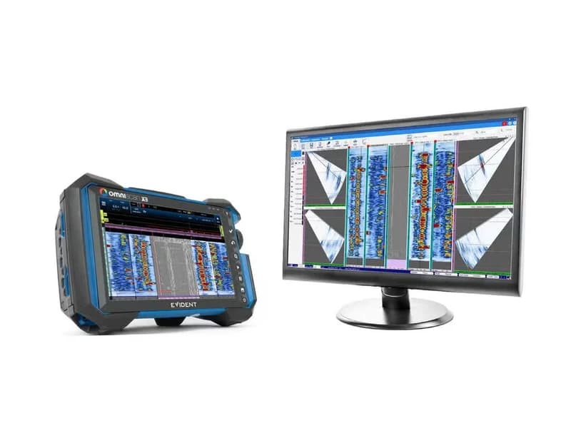
| Phased array (PAUT) | Multi-element probe, beam steered and focused electronically | Weld defects, corrosion maps, mid-wall damage such as hydrogen blistering and laminations | Higher cost, operator training required | Yes: OmniScan SX, X3, X4 |
| Eddy current | Eddy currents induced in a conductive material by an alternating magnetic field | Surface and near-surface cracks; also coating thickness and conductivity | Conductive materials only, limited depth; delaminations parallel to the coil winding are undetectable | Yes: NORTEC 600 |
| Magnetic particle | Leakage field over a defect holds magnetic particles | Surface and near-surface cracks | Ferromagnetic materials only; the defect must lie at 45–90° to the field | No |
| Penetrant (visible, fluorescent) | Penetrant enters the defect, developer draws it to the surface | Cracks and pores open to the surface | Surface-breaking defects only; non-porous materials; cleaning is critical | No |
| Radiography | X-rays or gamma rays pass through the part onto film or a digital detector | Porosity, slag inclusions, lack of penetration in welds and castings | Source and detector on opposite sides of the part; radiation safety | No |
| Acoustic emission | Sensors listen for elastic waves from growing defects under load | Growing cracks, leaks, active structural defects | Load required; qualitative assessment, size determined by another method; noise interferes | No |
Visual and remote visual inspection
Visual inspection is the first and most widely used method. Remote visual inspection (RVI) is done with a videoscope: a camera, a light source and a flexible or rigid insertion tube that sends live video from areas that cannot be reached without disassembly. It finds cracks, corrosion and foreign object debris in turbines, boilers, engines, pipelines and vessels. Many videoscopes offer 3D measurement to assess defect size.
The choice depends on the access path: according to Evident, 2–4 mm probes suit narrow spaces, while 6–8 mm probes are more durable and give better images. Tip articulation also matters, and hazardous areas require certified equipment. How to choose a model is covered in Which IPLEX videoscope to choose.
Equipment covered in this article
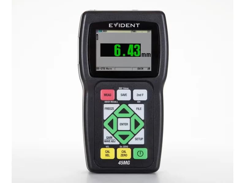
Olympus 45MG — ultrasonic thickness gauge
Olympus (Evident) ultrasonic thickness gauge: 0.08–635 mm, dual and single element transducers, Echo-to-Echo and THRU-COAT options for measuring through coatings, up to…
Ultrasonic thickness gauging
A thickness gauge measures how long a pulse takes to cross the wall to the back surface and return, and calculates thickness as T = V × t/2, where V is the sound velocity in the material and t is the round-trip transit time. Access from one side is enough. Typical frequencies are 500 kHz to 20 MHz: higher frequencies measure thin materials, lower ones penetrate thick and coarse-grained materials better. The gauge must be calibrated to the sound velocity on a reference of known thickness. More in Ultrasonic thickness gauge: operating principle.
Ultrasonic flaw detection
A flaw detector sends ultrasound into the material and receives echoes from discontinuities: cracks, voids, porosity. The echo arrival time gives the reflector position, and the signal can often indicate its size, shape and orientation. The method is sensitive to surface and subsurface defects, penetrates deeper than other NDT methods and needs access from one side only. Limitations according to the NDT Resource Center: couplant and reference standards are required, the operator must be well trained, rough, thin, inhomogeneous and coarse-grained materials (such as cast iron) are difficult, and a defect parallel to the beam may go undetected. How the instrument works is explained in Ultrasonic flaw detector: how it works and what it finds.
Phased array (PAUT)
A phased array probe contains 16 to 256 elements pulsed with small time delays. This lets the beam sweep through a range of angles (sectorial scanning) and focus at different depths without moving the probe. Typical frequencies are 2–10 MHz. According to Evident, the main PAUT tasks are weld inspection, crack detection and corrosion mapping, including telling wall loss apart from mid-wall damage such as hydrogen blistering. The drawbacks are higher cost and the need for training. When a thickness gauge is enough and when you need PAUT is covered in Thickness gauging, flaw detector or PAUT.
Eddy current testing
The alternating magnetic field of a coil induces eddy currents in a conductive material. Cracks and changes in dimensions or material properties disturb their flow, and the instrument registers this. Besides crack detection the method measures material and coating thickness and conductivity (material sorting, heat damage detection, heat treatment monitoring). The probe does not need to touch the surface, and preparation is minimal. Limitations: conductive materials only, limited depth of penetration, operator training and reference standards required.
Magnetic particle testing
The part is magnetised; surface and near-surface defects create a leakage field that gathers magnetic particles into a visible indication. The method is fast, less demanding on surface preparation and is used on castings, forgings and welds. The limitation is ferromagnetic materials only. A defect is detected when it lies at 45–90° to the magnetic field, so parts are normally magnetised in two directions at right angles.
Penetrant testing
A visible or fluorescent penetrant is applied to a cleaned surface; after a dwell time (typically 5 to 60 minutes) the excess is removed and a developer draws the penetrant out of defects (development usually takes at least 10 minutes). The method is sensitive to small surface defects and works on metals and non-metals, magnetic and non-magnetic materials. But it sees only surface-breaking defects, requires a non-porous surface, thorough cleaning and chemical disposal.
Radiographic testing
X-rays or gamma rays pass through the part onto film or a digital detector on the opposite side. Density changes in the image reveal porosity, slag inclusions, lack of penetration and other weld and casting defects. For thick metal a Co-60 source can be used, for thin and low-density materials a low-energy Tm-170 source. Working with radiation requires radiation safety measures.
Acoustic emission testing
The method does not send energy into the object; it listens for elastic waves released by crack growth, plastic deformation and other processes under load. So it detects only active, growing defects and can be applied to operating structures with permanently mounted sensors. Limitations: if the load is too low, a defect will not show; the assessment is qualitative, and size and depth are determined by another method, most often ultrasound; plant noise interferes.
How to choose a method
- Where the defect is: surface only — visual, penetrant, magnetic particle, eddy current; internal — ultrasound, PAUT or radiography.
- What the part is made of: magnetic particle only for ferromagnetic steels, eddy current for conductive materials, penetrant for any non-porous material.
- What access you have: one side — ultrasound; through a port or hole — videoscope; radiography needs access from both sides.
- What you need to obtain: thickness — thickness gauge; presence and size of a defect — flaw detector or PAUT; a corrosion map or weld image — PAUT.
Which equipment to choose
- Remote visual inspection — videoscopes IPLEX NX, IPLEX One.
- Corrosion thickness gauging — 45MG, 27MG.
- Ultrasonic flaw detection — EPOCH 650.
- Phased array — OmniScan X3, OmniScan X4.
- Eddy current testing — NORTEC 600.
KEG TRK supplies Evident (Olympus) equipment for these methods in Kazakhstan. Our catalogue does not include equipment for magnetic particle, penetrant, radiographic or acoustic emission testing. Price on request.
Sources
- NDT Resource Center (nde-ed.org). Nondestructive Evaluation Techniques.
- NDT Resource Center. Basic Principles of Ultrasonic Testing.
- NDT Resource Center. Basic Principles of Eddy Current Inspection.
- NDT Resource Center. Introduction to Magnetic Particle Inspection, Magnetic Field Orientation and Flaw Detectability.
- NDT Resource Center. Liquid Penetrant Inspection Process, Advantages and Disadvantages of Penetrant Testing.
- NDT Resource Center. Present State of Radiography, Radiograph Interpretation — Welds.
- NDT Resource Center. Introduction to Acoustic Emission Testing.
- Evident. Thickness Gauge Tutorial: Theory of Operation.
- Evident. Ultrasonic Flaw Detection Tutorial: General Introduction.
- Evident. Introduction to Phased Array Ultrasonic Testing, Practical applications and advantages of phased array.
- Evident. Your Complete Guide to Remote Visual Inspection (RVI).
Frequently asked questions
Equipment in this article
KEG TRK quotes prices and delivery times to Kazakhstan on request. We will prepare a commercial offer for your application.
Olympus 45MG — ultrasonic thickness gauge
Olympus (Evident) ultrasonic thickness gauge: 0.08–635 mm, dual and single element transducers, Echo-to-Echo and THRU-COAT options for measuring through coatings, up to…
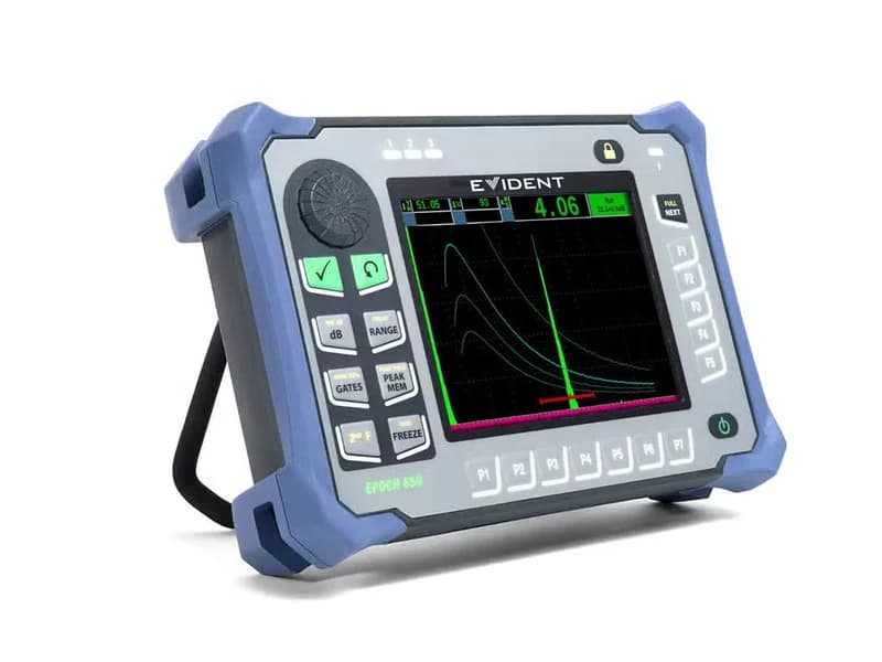
Olympus EPOCH 650 — ultrasonic flaw detector
Portable Olympus (Evident) ultrasonic flaw detector: tunable square-wave pulser up to 400 V, 0.2–26.5 MHz bandwidth, VGA display, DGS/AVG, DAC/TCG and AWS as standard…
Also in this article: Olympus OmniScan X3 — phased array flaw detector with TFM, Olympus NORTEC 600 — eddy current flaw detector, Olympus IPLEX NX — flagship industrial videoscope
Read also
10/13/2026
Thickness Gauging Through Paint: Echo-to-Echo and THRU-COAT Modes
Why a standard gauge overstates painted steel thickness, how echo-to-echo and THRU-COAT remove the coating, which transducers they need, thickness ranges and temperature limits.
10/13/2026
Ultrasonic Flaw Detector: How It Works and What It Finds
The pulse-echo principle, how to read an A-scan, straight and angle beam transducers, which flaws a detector finds, velocity and zero calibration, reference blocks and the DAC curve.
10/10/2026
How to Measure Pipe Wall Thickness with an Ultrasonic Thickness Gauge
Corroded pipe wall thickness is measured with an ultrasonic gauge and a dual element transducer: clean the spot, apply couplant, calibrate sound velocity and zero, place the transducer with its barrier across the pipe axis and take the minimum reading.