
Ultrasonic Flaw Detector: How It Works and What It Finds
The pulse-echo principle, how to read an A-scan, straight and angle beam transducers, which flaws a detector finds, velocity and zero calibration, reference blocks and the DAC curve.
An ultrasonic flaw detector sends a short ultrasonic pulse into a part and receives echoes from cracks, voids and material boundaries. On the A-scan, the echo position shows the reflector's depth and the echo height shows how strongly it reflects. Straight beam transducers are used to find laminations and voids; angle beam transducers are used for weld flaws.
The pulse-echo principle
The method relies on high-frequency sound travelling through solid material and reflecting from hidden flaws and boundaries in predictable ways. According to Evident's tutorial:
- flaw detection usually uses frequencies from 500 kHz to 10 MHz, while human hearing reaches about 20 kHz;
- at megahertz frequencies sound travels poorly through air and gases but well through liquids, metals, plastics, ceramics and composites, so couplant is applied between transducer and part;
- high-frequency ultrasound is more directional than audible sound, and its short wavelength makes it sensitive to small reflectors.
The sequence:
- The pulser sends an electrical pulse to the transducer, which emits ultrasound.
- Sound travels through the part. If a crack or discontinuity lies in its path, part of the energy reflects from it and the rest continues to the back wall.
- The receiver amplifies and filters the returning echoes.
- The instrument displays them on a calibrated depth or distance scale, and alarm gates flag echoes in a selected zone.
A thickness gauge uses the same principle but displays a single number, whereas a flaw detector shows the full signal pattern. The gauge is covered in Ultrasonic Thickness Gauge: Operating Principle and Limitations.
What a flaw detector consists of
| Block | Function |
|---|---|
| Pulser and receiver | Generates the excitation pulse, amplifies and filters echoes. Pulse amplitude, shape, damping, gain and receiver bandwidth are adjustable to improve signal-to-noise ratio |
| Clock | Synchronises pulses and provides distance calibration |
| Signal processing | From a simple amplitude-versus-time display to distance/amplitude correction and trigonometric calculations for angled sound paths |
| Display | Shows the signal on a depth or distance scale |
| Data logger | Stores the waveform and setup or selected data: amplitude, depth, alarm status |
Equipment covered in this article
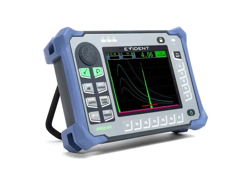
Olympus EPOCH 650 — ultrasonic flaw detector
Portable Olympus (Evident) ultrasonic flaw detector: tunable square-wave pulser up to 400 V, 0.2–26.5 MHz bandwidth, VGA display, DGS/AVG, DAC/TCG and AWS as standard…
How to read an A-scan
The A-scan is the basic flaw detector display. The horizontal axis, left to right, is pulse travel time, meaning sound path or depth. The vertical axis is echo amplitude.
| On screen | Meaning (straight beam) |
|---|---|
| Back wall echo only | Sound reached the back wall without obstruction |
| Echo ahead of the back wall | Part of the sound reflected from a flaw. Echo position gives depth; amplitude correlates with reflector size |
Before inspection, record the echo pattern from a known good part: the back wall echo and fixed echoes from geometry (grooves, flanges). Grain scatter noise is not counted as a flaw. Any significant echo ahead of the back wall indicates a crack or void parallel to the surface and calls for further analysis of depth, size and shape.
Straight beam transducers
A straight beam transducer sends a longitudinal wave into the part perpendicular to the surface. Straight beam testing uses contact, delay line, dual element and immersion transducers.
What they find: mainly cracks and delaminations parallel to the surface, as well as voids and porosity.
Where they are used: plate, bar, forgings, castings; bolts, hanger pins and other parts that can crack parallel to an accessible surface; fiberglass and composites. Braze joints are also checked with a straight beam: a lack of bonding returns a larger echo from the bondline, so testing is done by comparison with a good sample.
Angle beam transducers and weld inspection
According to Evident, angle beam testing is by far the most commonly used technique in ultrasonic flaw detection. Weld flaws are usually not parallel to the surface and the weld crown prevents placing a probe on top, so the weld is inspected from the side at an angle.
An angle beam probe consists of a transducer and a wedge (separate or integrated). Refraction at the wedge-to-part boundary generates a shear wave in the metal. The standard refracted angles in steel are 45, 60 and 70 degrees. The beam travels at that angle to the bottom surface, reflects at the same angle and travels upward. Moving the probe back and forth sweeps the beam across the full weld height and the fusion lines.
How typical weld flaws appear on the A-scan according to Evident's tutorial:
| Flaw | Signal character |
|---|---|
| Incomplete penetration | Very strong reflection from the weld root, seen from either side |
| Lack of fusion | Strong reflection with fast rise and fall from the bevel side; weaker or absent from the opposite side |
| Root crack | First-leg signal close to the root bead echo |
| Toe crack | Second-leg signal near the top surface, close to the crown echo |
| Porosity and slag | A cluster of echoes whose shape and amplitude change rapidly as the probe is rotated; generally weaker than echoes from planar flaws and large cracks |
Evident states that these examples are for illustration only, and that waveform interpretation always requires proper operator training and experience and knowledge of the specific test requirements.
Flaw length. When an indication appears, the probe is moved to peak amplitude, then moved across the flaw, noting the two positions where amplitude falls to 50% of the peak (a 6 dB drop). The distance between them is taken as the flaw size. Other procedures may use a different reference level.
Calibration and reference blocks
Evident distinguishes three kinds of calibration.
| Kind | What is done | Using |
|---|---|---|
| Velocity and zero | The instrument is given the material sound velocity and a zero offset (wedge, cable and couplant delay) to convert time into distance | Two-point method on two reflectors at known distances, often on an IIW block |
| Reference | A reference signal amplitude is set for comparison with indications in the part | Reference standards per the user's procedure; for angle beam, an IIW Type 1 or ASTM E-164 block and its side-drilled hole |
| Instrument certification | Checks horizontal and vertical linearity | To a standard such as ASTM E-317 or EN 12668 |
Key rules:
- measurements are only as accurate as the velocity and zero calibration;
- the block must be made of the same material as the part: calibration blocks are available in several steel alloys, aluminum and titanium;
- sound velocity depends on density, elasticity, composition, grain structure and temperature.
DAC and TVG. Echoes from identical reflectors weaken with depth because of attenuation and beam spreading. A DAC curve is built from reflectors of one size at different depths: an echo from a calibration-size reflector falls on the curve at any depth, a larger reflector gives an echo above it and a smaller one below. TVG solves the same problem without a curve: gain increases with sound path so all reference echoes reach the same height, typically 80% of the screen.
Limitations
- Couplant or immersion is required: megahertz ultrasound does not cross an air gap.
- A straight beam is poorly suited to flaws not parallel to the surface, which is why welds are inspected with an angle beam.
- Grain scatter noise is present on the screen, and the operator has to distinguish it from flaw indications.
- Results depend on calibration, reference blocks and operator qualification. Tutorials do not replace training, hands-on practice and the requirements of applicable codes.
When a thickness gauge is enough, when an EPOCH flaw detector is needed and when phased array is justified is covered in Thickness Gauging, Flaw Detector or PAUT.
Which instrument to choose
- Weld, pressure vessel and forging inspection with flaw sizing: the EPOCH 650, with DGS/AVG, DAC/TCG and AWS D1.1/D1.5 as standard.
- One-handed work at height and on rope access: the EPOCH 6LT, weighing 890 g.
KEG TRK supplies Evident (Olympus) ultrasonic flaw detectors in Kazakhstan. Price on request.
Sources
- Evident. Ultrasonic Flaw Detection Tutorial.
- Evident. General Introduction.
- Evident. What is Ultrasound?.
- Evident. General Description.
- Evident. Calibration Concepts.
- Evident. 4.3 Typical Angle Beam Setup Procedure.
- Evident. 5.1 Straight Beam Tests.
- Evident. 5.2 Angle Beam Inspection.
- Evident. 6.6 Basic Waveform Interpretation.
- Evident. DAC/TVG.
Frequently asked questions
Equipment in this article
KEG TRK quotes prices and delivery times to Kazakhstan on request. We will prepare a commercial offer for your application.
Olympus EPOCH 650 — ultrasonic flaw detector
Portable Olympus (Evident) ultrasonic flaw detector: tunable square-wave pulser up to 400 V, 0.2–26.5 MHz bandwidth, VGA display, DGS/AVG, DAC/TCG and AWS as standard…
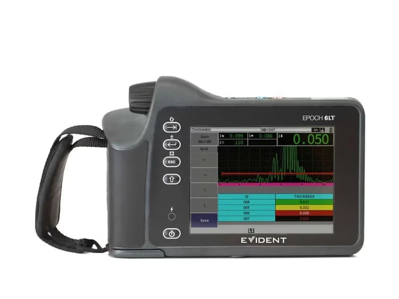
Olympus EPOCH 6LT — lightweight ultrasonic flaw detector
Lightweight Olympus (Evident) ultrasonic flaw detector, 890 g, for one-handed and rope access work: pulser up to 400 V, bandwidth up to 26.5 MHz, VGA display, 100,000…
Read also
10/13/2026
Acoustic Camera: What It Is and How It Works
How an acoustic camera with a MEMS microphone array shows an ultrasound source on video, what beamforming is, which tasks it handles and where the method has limits.
10/13/2026
Thickness Gauging Through Paint: Echo-to-Echo and THRU-COAT Modes
Why a standard gauge overstates painted steel thickness, how echo-to-echo and THRU-COAT remove the coating, which transducers they need, thickness ranges and temperature limits.
10/10/2026
How to Measure Pipe Wall Thickness with an Ultrasonic Thickness Gauge
Corroded pipe wall thickness is measured with an ultrasonic gauge and a dual element transducer: clean the spot, apply couplant, calibrate sound velocity and zero, place the transducer with its barrier across the pipe axis and take the minimum reading.