
Acoustic Camera: What It Is and How It Works
How an acoustic camera with a MEMS microphone array shows an ultrasound source on video, what beamforming is, which tasks it handles and where the method has limits.
An acoustic camera is an instrument that locates sound sources and shows them as a colour map over live video. Inside it has an array of dozens of MEMS microphones, an optical camera and software that calculates where the sound comes from using the difference in arrival time at each microphone. This makes leaks, electrical discharges and noisy mechanical components visible.
What an acoustic camera consists of
According to Crysound, an acoustic camera combines three parts:
- Microphone array. Typically from 64 to more than 200 MEMS microphones arranged in a circle, spiral or grid. Crysound classes 64 microphones as entry level and 128 as professional grade.
- Optical camera that records video of the scene.
- Processing software that builds a map of sound sources and overlays it on the video.
For example, the SDT SonaVu has 112 digital MEMS sensors, a sample rate of 96,000 samples per second and an image refreshed at 25 frames per second on a 5-inch touch screen. The Crysound CRY2620 has 64 MEMS microphones in a 12 cm array; the CRY2623 has 128.
How the camera finds the source: beamforming
Sound from a source reaches each microphone of the array with a slightly different delay because the distances differ. The software then works as follows:
- For each point in the field of view it calculates the delays with which sound from that point would reach each microphone.
- It shifts the signals of all channels by those delays and sums them.
- If there really is a source at that point, the signals add up and the sum is large. For other points they partly cancel.
- It repeats the calculation for every point in the frame and obtains an intensity map, shown in colour over the video.
This method is called beamforming. Crysound compares the result to a thermal camera: instead of hot spots, the screen shows loud spots.
The array geometry sets the frequency limits. The low-frequency limit is governed by the overall array diameter: the larger the array, the lower the frequencies it resolves. The high-frequency limit depends on microphone spacing: the closer the spacing, the higher the frequency before spatial aliasing occurs.
Equipment covered in this article
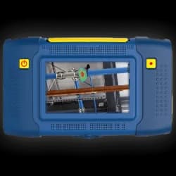
SDT SonaVu - Acoustic Camera for Equipment Diagnostics
SonaVu acoustic camera with 112 sensors and a built-in 5-inch touchscreen for visualising air leaks, electrical discharges and mechanical defects from up to 50 metres…
Why the camera listens to ultrasound
According to SDT, leaks, partial discharge and steam traps create turbulence, and turbulence produces ultrasound that travels through the air.
Typical frequency ranges by task according to Crysound:
| Task | Typical range |
|---|---|
| Compressed air leaks | 20–50 kHz |
| Partial discharge | 20–100 kHz |
| Mechanical faults | 1–20 kHz |
A camera limited to 20 kHz is suitable only for audible noise analysis. SonaVu provides filtering by a selected frequency range and image averaging, so the operator isolates the band in which the target source sounds.
What tasks an acoustic camera handles
| Task | What the operator sees | According to the manufacturers |
|---|---|---|
| Compressed air, gas and vacuum leaks | The leak point on a pipe, fitting or valve | The Crysound CRY2620 and CRY2623 estimate leak rate and cost; SDT produces reports and leak cost estimates in the InSights web app |
| Fugitive gas emissions | Leaks from high-pressure areas: pipes, valves | SDT lists this application for oil and gas facilities |
| Partial and corona discharge | The discharge location on switchgear, a transformer, an overhead line or a cable | The CRY2623 localises discharges, distinguishes surface, suspension and corona discharge and builds a PRPD pattern in real time |
| Steam traps | A working or failed steam trap | SDT lists them as sources of airborne ultrasound |
| Mechanical | Bearing wear, gearbox noise, leaking valves | Crysound places these tasks in the 1–20 kHz range |
More on specific tasks:
- survey route and leak search procedure: How to Find Compressed Air Leaks in a Plant;
- ultrasonic partial discharge inspection: Partial Discharge in Switchgear and Substations;
- corona at substations: Corona Discharge at a Substation.
SonaVu stores images and video, which are used in the survey report.
Limitations of the method
- Resolution. Beamforming resolution is limited by wavelength and array size. Angular resolution depends on frequency and distance, and a larger array separates closely spaced sources better.
- Distance. Beamforming is designed for the far field, roughly from 1 m. Detection range depends on leak size, background noise, microphone count and frequency range. Crysound estimates that a typical handheld camera sees a 1 mm compressed air leak from 10 to 30 m.
- Background ultrasound. In a noisy plant the source is harder to isolate. SDT recommends setting camera sensitivity to the background level in the area being surveyed. More microphones give better noise rejection.
- Outdoor sites. According to Crysound, outdoor work requires wind noise rejection and a weather-resistant design.
- Hazardous areas. A certified version is required, such as the SonaVu ATEX or CRY2624 ATEX.
- Interpretation. The camera shows where the sound source is, but classifying partial discharge and complex patterns requires operator training.
Example specifications
| Parameter | SDT SonaVu | Crysound CRY2620 | Crysound CRY2623 |
|---|---|---|---|
| Microphones | 112 MEMS | 64 MEMS | 128 MEMS |
| Frequency range | 1–47.5 kHz | 2–40 kHz | 2–48 kHz |
| Distance | 0.3–50 m | 0.5–70 m | 0.3–120 m |
| Screen | 5", 800 × 480 | 7", 1024 × 600 | 7", 1024 × 600 |
| Weight | 1.2 kg | 1.7 kg | 1.7 kg |
Specifications are taken from official SDT and Crysound materials. Which camera fits a given task and budget is covered in SonaVu or Crysound: Which Acoustic Camera to Choose in 2026.
Which instrument to choose
- Leaks, electrical and mechanical inspection with one instrument, reports in InSights: the SDT SonaVu.
- Leaks and partial discharge with PRPD and leak cost estimates: the Crysound CRY2623.
KEG TRK supplies SonaVu and Crysound acoustic cameras in Kazakhstan. Price on request.
Sources
- Crysound. Acoustic Camera: How It Works, Types & Applications.
- Crysound. CRY2620 64-Mic Industrial Acoustic Imaging Camera.
- Crysound. CRY2623 128-Mic Industrial Acoustic Imaging Camera.
- SDT Ultrasound Solutions. SonaVu Acoustic Imaging Camera.
- SDT Ultrasound Solutions. SonaVu Brochure (PDF).
Frequently asked questions
Equipment in this article
KEG TRK quotes prices and delivery times to Kazakhstan on request. We will prepare a commercial offer for your application.
SDT SonaVu - Acoustic Camera for Equipment Diagnostics
SonaVu acoustic camera with 112 sensors and a built-in 5-inch touchscreen for visualising air leaks, electrical discharges and mechanical defects from up to 50 metres…
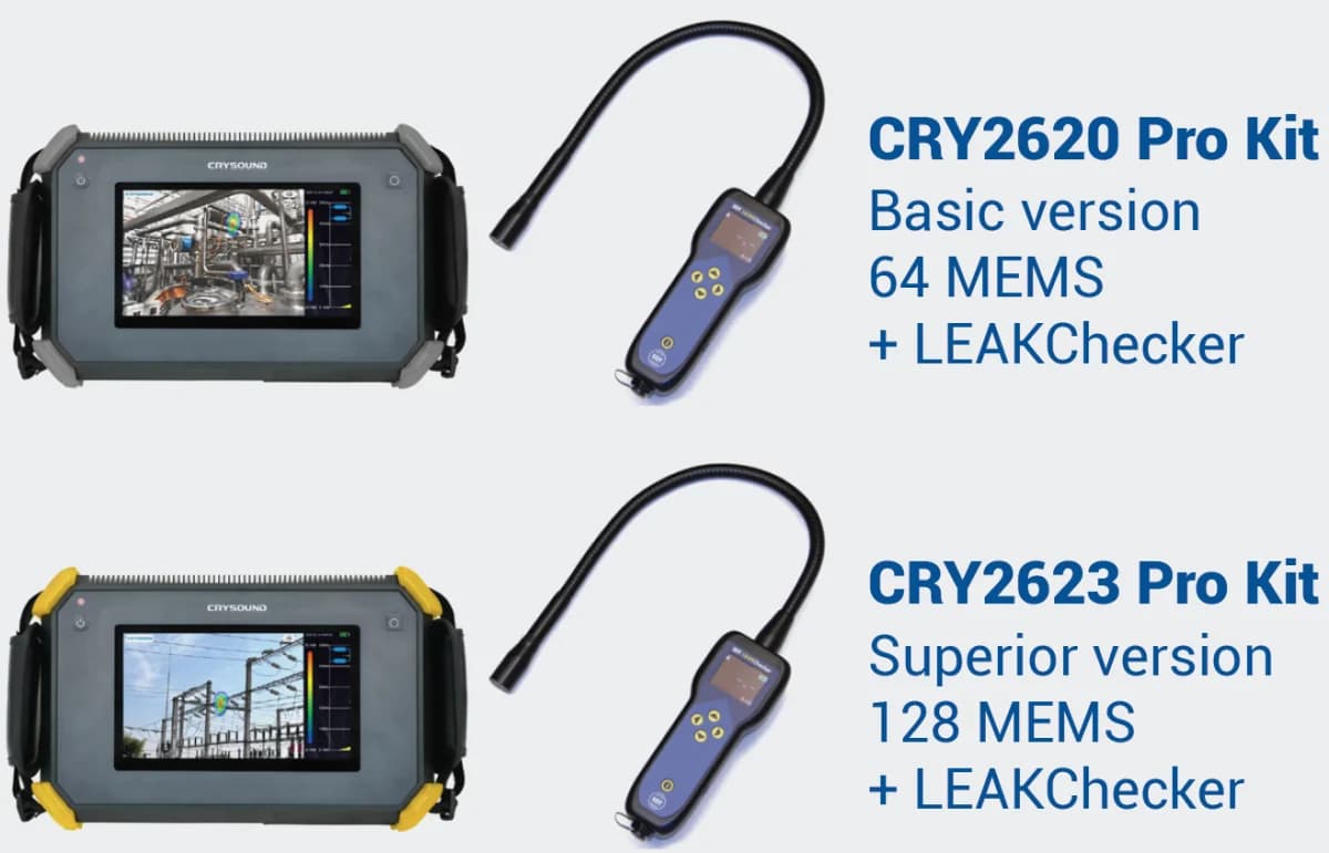
Crysound CRY2623 — Acoustic Camera for Leaks and Partial Discharge
Advanced Crysound CRY2623 acoustic camera with 128 MEMS sensors: leak visualisation and partial-discharge detection with PRPD maps. Range up to 120 metres.
Read also
10/13/2026
Thickness Gauging Through Paint: Echo-to-Echo and THRU-COAT Modes
Why a standard gauge overstates painted steel thickness, how echo-to-echo and THRU-COAT remove the coating, which transducers they need, thickness ranges and temperature limits.
10/13/2026
Ultrasonic Flaw Detector: How It Works and What It Finds
The pulse-echo principle, how to read an A-scan, straight and angle beam transducers, which flaws a detector finds, velocity and zero calibration, reference blocks and the DAC curve.
10/10/2026
How to Measure Pipe Wall Thickness with an Ultrasonic Thickness Gauge
Corroded pipe wall thickness is measured with an ultrasonic gauge and a dual element transducer: clean the spot, apply couplant, calibrate sound velocity and zero, place the transducer with its barrier across the pipe axis and take the minimum reading.