
Ultrasonic Thickness Gauge: How It Works and Its Limitations
How an ultrasonic thickness gauge calculates thickness from an echo, contact, delay line, immersion and dual element transducers, measurement modes, what affects accuracy and where the method fails.
An ultrasonic thickness gauge sends a short ultrasonic pulse into the wall and measures how long the echo from the opposite surface takes to return to the transducer. It calculates thickness as T = V × t / 2, where V is the sound velocity in the material. One-sided access is enough; accuracy depends on calibration, transducer and surface.
The pulse-echo principle
Per the Evident tutorial, every ultrasonic thickness gauge works by precise timing:
- The pulser applies a short electrical impulse to the transducer's piezoelectric element, which emits a burst of ultrasonic waves.
- The wave enters the material through couplant and travels to the back wall or another boundary, such as air or liquid inside a pipe.
- The reflected echo returns, and the transducer converts it back into an electrical signal.
- The gauge measures the time interval (typically a few millionths of a second), usually several times for averaging, and calculates thickness:
T = V × t / 2, where T is thickness, V is sound velocity in the material and t is the round-trip transit time. In some cases a zero offset for fixed delays in the instrument, cable and transducer is also subtracted.
Sound velocity is an essential part of the calculation. Typical values and the calibration procedure are in "Sound velocity in materials: a table for thickness gauging".
Frequency. Ultrasonic testing is most commonly done between 500 kHz and 20 MHz. Higher frequencies (5 MHz and above) give better resolution in thin materials; lower ones (2.25 MHz and below) give better penetration in thick, highly attenuating and scattering materials such as fiberglass and coarse-grained castings.
Couplant. Megahertz ultrasound does not travel efficiently through air, so a drop of glycerin, propylene glycol, water, oil or gel is applied between transducer and part, just enough to fill the thin air gap.
Corrosion gauges and precision gauges
Evident divides thickness gauges into two types:
| Corrosion gauge | Precision gauge | |
|---|---|---|
| Transducer | Dual element | Single element |
| Task | Remaining wall of pipes, tanks and pressure vessels with internal corrosion | All other thickness measurement: metals, plastics, glass, composites |
| Strength | Sensitive to pitting and localized thinning, tolerates hot surfaces | Higher inherent accuracy |
| Limitation | V-shaped sound path needs a trigonometric correction, zero drift is possible | Less effective than a dual at finding pitting; contact transducers only up to approximately 50 °C |
Equipment covered in this article
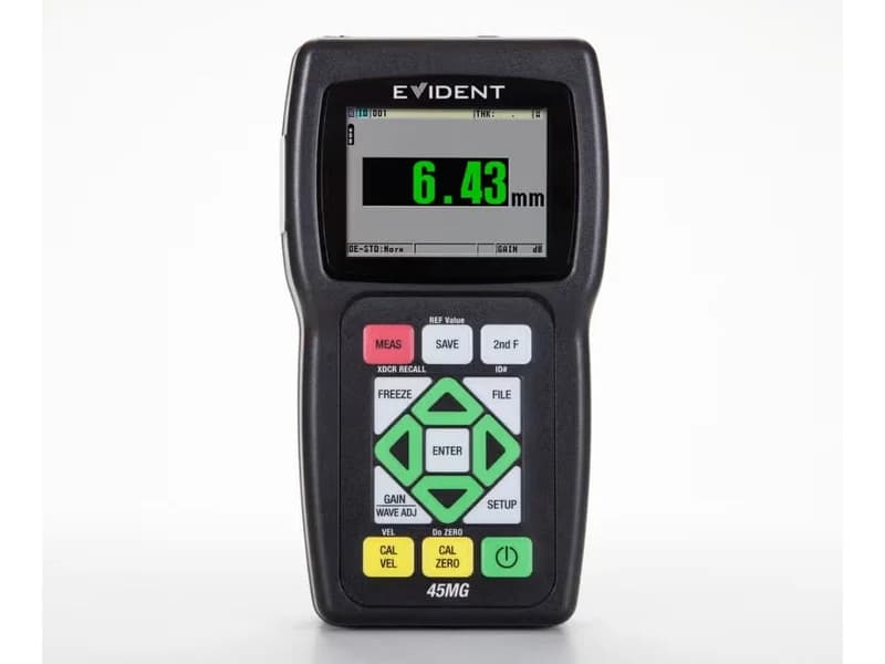
Olympus 45MG — ultrasonic thickness gauge
Olympus (Evident) ultrasonic thickness gauge: 0.08–635 mm, dual and single element transducers, Echo-to-Echo and THRU-COAT options for measuring through coatings, up to…
Transducer types
A single element transducer contains a piezoceramic element protected by a wearplate or acoustic lens, with a damping backing that quiets it after the pulse. A dual element transducer is built differently: two elements separated by a sound barrier, no backing, and sound coupled through integral delay lines.
| Transducer | How sound enters | Typical use |
|---|---|---|
| Contact | Directly through a wearplate | Greatest maximum thickness, good penetration in castings, low density plastics, rubber |
| Delay line | Through an insert (delay line) between element and part | Thin materials, plastics and composites, small radii, hot surfaces (with a heat-resistant delay line) |
| Immersion | Through a water bath or water column | Very small radii (focused), in-line measurement of moving material: pipe, cable jacket, sheet |
| Dual element | Separate transmitter and receiver on delay lines, V-shaped sound path | Corrosion: remaining wall from the inside, hot pipes |
In general, the most repeatable results come from the highest frequency and smallest diameter transducer that still covers the required thickness range.
Measurement modes
With single element transducers, the time interval is measured in one of three ways:
| Mode | What is timed | Advantages | Disadvantages |
|---|---|---|---|
| Mode 1 (contact transducer) | From the excitation pulse to the first back wall echo, minus zero offset | Greatest maximum thickness, best penetration | Higher minimum thickness, accuracy depends on coupling, only up to approximately 50 °C |
| Mode 2 (delay line or immersion) | From the interface echo to the first back wall echo | Near-surface resolution in plastics and composites, hot measurements, small radii, in-line measurement | Maximum thickness limited by delay line length |
| Mode 3 (delay line or immersion) | Between two successive back wall echoes | Highest accuracy and best minimum thickness resolution, removes thin paint | Needs clean multiple back wall echoes: fine-grained metals, ceramics, glass |
Dual element transducers usually work in Mode 1 with a large zero offset for the delay line transit time and a correction for the V-shaped sound path.
What affects accuracy
Calibration. Evident stresses that a measurement is only as accurate as the velocity and zero calibration. Recalibrate when the material or transducer changes and when the temperature changes significantly.
Material.
- Scattering from grain and fiber boundaries in cast stainless steel, cast iron, fiberglass and composites, and from porosity.
- Attenuation in low density plastics and rubber, which increases with temperature and limits maximum thickness.
- Non-uniform sound velocity: in castings because of varying grain structure, in fiberglass because of a varying resin/fiber ratio.
- Echo phase reversal, for example with glass or plastic liners over metal or copper cladding over steel: the detection polarity must be changed.
Geometry and surface.
- A rough surface raises the minimum measurable thickness and distorts the echo. Remove loose rust, scale and flaking paint.
- On a curved surface, center the transducer and keep it normal to the surface; the smaller the radius, the smaller the transducer should be. Excess couplant on a curve causes spurious signals.
- If the walls are not parallel (taper, eccentricity), the echo weakens and distorts, and the reading is roughly the average thickness within the beam.
Operator. In Mode 1 the couplant layer is part of the measurement, so use a consistent amount of couplant and consistent pressure. Tilting distorts the echo. Never drag the transducer across a rough surface.
Coatings. Sound velocity in nonmetallic coatings is usually about half that of steel, so paint can add an error of double its actual thickness. Echo-to-echo and THRU-COAT modes exist for this case.
Limitations of the method
- Couplant and a prepared spot are required: ultrasound does not cross an air gap.
- Temperature. Standard contact transducers are damaged above approximately 50 °C. Hot surfaces need dual element transducers (some models up to 500 °C in brief contact) or delay line and immersion transducers in Mode 2 or 3, and above approximately 100 °C a high-temperature couplant.
- Minimum and maximum thickness depend on transducer, mode and material. Below the transducer's minimum, false high readings are possible.
- Highly attenuating materials (rubber, fiberglass, many composites) need low frequency transducers and high penetration instruments.
- Dual element transducers are not recommended for precision gauging because of possible zero drift and timing imprecision from the V-shaped path.
- Long cables and submersion. With cables longer than about 3 m, cable effects must be considered. Standard transducers can be briefly immersed in shallow water; long-term submersion or depths beyond about 2 m need sealed transducers.
- A thickness gauge is not a flaw detector. It measures thickness at a point and is not meant to find and evaluate cracks, lack of fusion or laminations. The difference is explained in "Thickness gauging, flaw detector or PAUT".
A step-by-step procedure for a corroded pipe is in "How to measure pipe wall thickness with ultrasound".
Which gauge to choose
- Corrosion monitoring of pipes and vessels — 45MG: dual element transducers as standard, optional echo-to-echo, THRU-COAT and single element transducers.
- Precision measurement with single element transducers, multilayer materials, measurement through coatings — 39DL PLUS.
Model comparison is in "Which Olympus thickness gauge to choose"; to match a model to your task, use the thickness gauge selector. KEG TRK supplies Evident (Olympus) thickness gauges in Kazakhstan. Price on request.
Sources
- Evident. Theory of Operation.
- Evident. Types of Ultrasonic Thickness Gauges.
- Evident. Transducer Construction.
- Evident. Transducer Selection.
- Evident. How Do Ultrasonic Thickness Gauges Work? (Modes of Measurement).
- Evident. Measurements Through Coatings.
- Evident. Factors Affecting Measurement.
- Evident. How to Use Ultrasonic Thickness Gauges in Special Conditions.
Frequently asked questions
Equipment in this article
KEG TRK quotes prices and delivery times to Kazakhstan on request. We will prepare a commercial offer for your application.
Olympus 45MG — ultrasonic thickness gauge
Olympus (Evident) ultrasonic thickness gauge: 0.08–635 mm, dual and single element transducers, Echo-to-Echo and THRU-COAT options for measuring through coatings, up to…
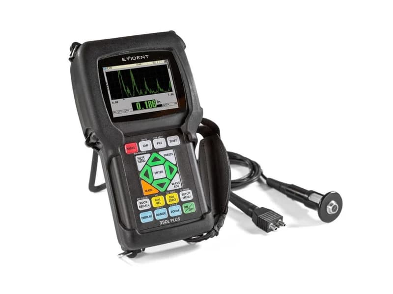
Olympus 39DL PLUS — ultrasonic thickness gauge
General-purpose Olympus (Evident) ultrasonic thickness gauge, successor to the 38DL PLUS: 0.08–635 mm, up to 60 Hz update, single and dual element transducers…
Read also
10/13/2026
Thickness Gauging Through Paint: Echo-to-Echo and THRU-COAT Modes
Why a standard gauge overstates painted steel thickness, how echo-to-echo and THRU-COAT remove the coating, which transducers they need, thickness ranges and temperature limits.
10/10/2026
Sound Velocity in Materials: A Table for Thickness Gauging
Longitudinal ultrasonic velocity in steels, aluminum, copper, cast iron and plastics per Evident data (m/s and in/µs). Why velocity is calibrated on a sample and how temperature affects it.
10/10/2026
How to Measure Pipe Wall Thickness with an Ultrasonic Thickness Gauge
Corroded pipe wall thickness is measured with an ultrasonic gauge and a dual element transducer: clean the spot, apply couplant, calibrate sound velocity and zero, place the transducer with its barrier across the pipe axis and take the minimum reading.