
How to Measure Vibration Correctly: Points, Directions, Sensor Mounting
Measure vibration on bearing housings, close to the bearing, in two radial directions and axially, at steady state. Mark each point and mount the sensor the same way every time.
In this article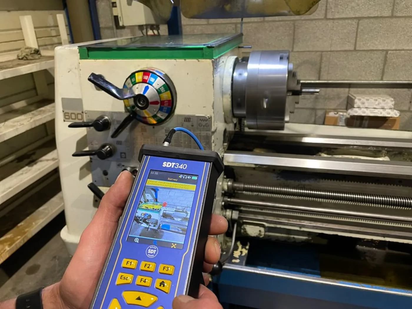
Prepared by the KEG TRK team · How we prepare our content
Vibration is measured on bearing housings, on a rigid part as close to the bearing as possible, in two radial directions (horizontal and vertical) and in the axial direction. The machine must be running at steady state. Each point is marked and listed on the route, and the sensor is placed in the same spot, at the same angle and with the same mounting every time. Otherwise the trend shows nothing.
Where to place the sensor
Brüel & Kjær states the main rule this way: place the sensor so that vibration from the bearing reaches it along a direct path. A sensor on the bearing housing sees mainly the bearing. A sensor beyond a joint or on a neighbouring part sees the same vibration modified by the joint and mixed with signals from other parts of the machine.
| Place it on | Avoid |
|---|---|
| A rigid bearing housing, close to the bearing | Fan covers, thin covers and guards |
| A flat clean pad | A rounded housing surface without a pad |
| A glued measurement pad | Rusty or painted surfaces |
| The same marked point | "Roughly the same place" |
A typical pump set has four bearing supports; the point layout for it is described in Pump vibration analysis.
Directions: horizontal, vertical, axial
Vibration is described in three mutually perpendicular directions:
- H (horizontal radial): across the shaft in the horizontal plane;
- V (vertical radial): across the shaft vertically;
- A (axial): along the shaft axis.
Specto Technology, referring to ISO 20816-1, notes that measuring in three directions fully characterizes machine vibration, while an incomplete set of directions is a common cause of wrong assessments. Brüel & Kjær advises that if not all directions can be measured, take at least the axial direction and one radial direction, the one expected to have the lowest stiffness.
Why directions matter: a fault may show strongly in only one of them. Mike Fitch (Ludeca) gives examples of 1x ratios that point the search in the right direction:
| Ratio of levels at 1x | Suggests |
|---|---|
| High axial and high horizontal | Misalignment or bent shaft |
| Low axial, vertical about 1.5 times horizontal | Looseness |
| Low axial, vertical about half of horizontal | Unbalance |
| Horizontal 75–100 times vertical and axial | Almost certainly resonance |
These are hints, not a diagnosis: the author stresses that phase and visual inspection are needed to confirm.
If time per machine is short, Adash suggests a compromise: a radial sensor at 45° to capture both horizontal and vertical components, plus one axial reading, for example near the coupling rather than on the motor bearing at the fan end.
Equipment covered in this article

vb7 — collector, analyzer and balancer
Dual channel simultaneous recording, two-plane balancing, IP65
Marking points and building a route
A trend only makes sense if every reading is taken in exactly the same place as the previous one. Brüel & Kjær notes that even adjacent points on one part can give significantly different levels and spectra, especially at high frequencies. So:
- Make a list of points (a route). Commtest calls it "a detailed shopping list": machine, point, direction and measurement parameter set.
- Give machines and points unique, meaningful names and label the equipment itself to match the list.
- Install measurement pads. Adash considers a glued flat stainless steel pad with a magnetic surface the best option: every analyst gets the same seat for the sensor.
- Before each reading, check the sensor orientation against the route.
- Keep the route short enough. With hundreds of sensor placements a day, carelessness creeps in; Mike Fitch recommends routes under 200 points.
Commtest's starting schedule: critical machines weekly, most machines monthly, less important ones every other month, then adjust with experience. Adash calls weekly measurement ideal and treats once a month as the minimum for critical machines. Measuring only every six months, in its view, is effectively run-to-failure.
Machine operating conditions
- Steady state. After start-up or a speed change, let the machine reach steady state, otherwise the spectrum will not reflect its true behaviour (Commtest).
- Same conditions. Only compare readings taken at comparable speed and load. Pump vibration depends strongly on the operating point, as described in Pump vibration analysis.
- Background. Vibration from nearby equipment can mask the machine's own vibration (Specto). How to check the background per ISO 10816-3 is described in Electric motor vibration limits per ISO 10816-3.
Sensor mounting
Mounting determines up to what frequency a measurement can be trusted: the stiffer and lighter the mounting, the higher the resonance of the sensor and its mount. A table of upper frequencies for a stud, adhesive, magnet and probe is in How to choose a vibration sensor. Practical conclusions from Brüel & Kjær:
- A stud on a flat smooth surface is ideal. A thin layer of grease under the base improves the stiffness of the joint.
- Cemented pads for permanent points: epoxy or cyanoacrylate adhesive; soft glue considerably reduces the usable frequency range.
- Magnet: convenient, but in Brüel & Kjær's test it lowered the sensor resonance to about 7 kHz, so it is not used much above 2 kHz.
- Hand-held probe: for quick checks only. Low stiffness can cause gross errors, results are not repeatable, and the band is limited to about 1000 Hz.
The sensor's main sensitivity axis must coincide with the required measurement direction.
Common mistakes
- Sensor on a fan cover, lid or paint instead of the rigid bearing housing.
- A new spot and angle every time: the trend shows placement scatter, not a change in condition.
- The direction set in the instrument does not match the actual sensor position.
- Reading taken right after start-up or at a different load.
- Mixed-up machines or points: one machine's spectrum is stored under another (Commtest warns this leads to wrong and costly conclusions).
- Bearing analysis based on hand-held probe data.
- Flat battery or full instrument memory in the middle of a route.
What vibration analysis gives you and how to build a programme is explained in What is equipment vibration analysis.
Which instrument to use
- Route collection, spectra and balancing: Bently Nevada vb7. According to the manufacturer's datasheet, it is a dual channel data collector for on-route and off-route readings, with spectra up to 6,400 lines, Fmax up to 40 kHz and an IP65 housing.
- Bearing ultrasound and vibration on one round: SDT340. It works with contact and airborne ultrasound sensors and with an accelerometer, shows the time signal and spectrum on screen, and recalls a point's history for trending.
KEG TRK supplies these instruments in Kazakhstan. Price on request.
Sources
- Brüel & Kjær. Measuring Vibration (BR 0094).
- Commtest Instruments. Beginner's Guide to Machine Vibration (published on Reliabilityweb).
- Mike Fitch, Ludeca. Location, Location, Location: Vibration Sensor Placement Is Crucial.
- Adash. How should I start my Predictive Maintenance Program?.
- Specto Technology. Machine Vibration Measurements.
- Bently Nevada. vb7 Portable Data Collector, Analyzer and Balancer, datasheet 116M5255 Rev. F.
- SDT Ultrasound Solutions. SDT340.
Frequently asked questions
Equipment in this article
KEG TRK quotes prices and delivery times to Kazakhstan on request. We will prepare a commercial offer for your application.
vb7 — collector, analyzer and balancer
Dual channel simultaneous recording, two-plane balancing, IP65
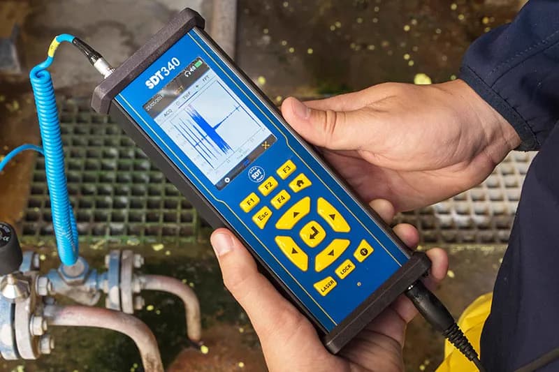
SDT340 - Advanced Ultrasound Detector
The most advanced ultrasound detector for collecting, analysing and trending data
Read also
10/10/2026
What Is Machinery Vibration Analysis and How to Start
Vibration analysis checks machine condition from bearing housing vibration: what is measured, route-based vs online monitoring, which faults show in the spectrum, how to start.
10/10/2026
Causes of Electric Motor Vibration and How to Tell Them Apart
Unbalance, misalignment, looseness, bearings, resonance, rotor and stator faults, driven machine problems. Which spectrum and waveform signs separate one cause from another.
10/10/2026
Vibration Meter or Vibration Analyser: Which to Choose
A vibration meter shows the overall level and tells you if there is a problem. An analyser adds the spectrum and waveform and shows the cause. A comparison by task, function and example instruments.