
Centrifugal Pump Vibration Analysis: Measurement Points, Faults, Limits
Pump vibration is measured on pump and motor bearing housings in three directions, compared with ISO 10816-7 zones, and diagnosed from the spectrum: 1x, 2x, harmonics, vane pass.
Centrifugal pump vibration is measured on the pump and motor bearing housings in the horizontal, vertical and axial directions at steady operation. The overall RMS velocity is compared with the ISO 10816-7 zones, and the cause is found in the spectrum: 1x means unbalance, 2x and axial content mean misalignment, a series of harmonics means looseness, non-synchronous peaks mean bearings, and vane pass means hydraulics.
Measurement points and directions
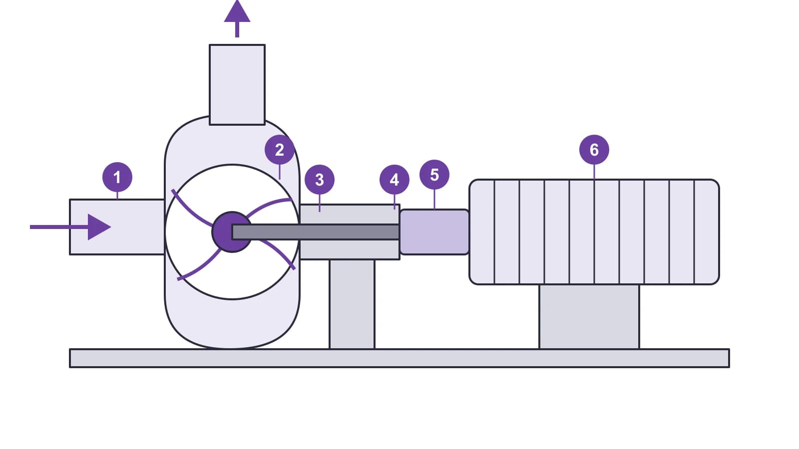
A typical horizontal motor + coupling + pump set has four bearing locations. A layout of pump components is in the article Centrifugal pump design: six components and how to monitor each.
| Point | Location | Directions |
|---|---|---|
| 1 | Motor bearing, fan end | Horizontal, vertical |
| 2 | Motor bearing, coupling end | Horizontal, vertical, axial |
| 3 | Pump bearing, coupling end | Horizontal, vertical, axial |
| 4 | Pump bearing, free end | Horizontal, vertical |
Rules that decide whether the data can be trusted:
- Mount the sensor on a rigid part of the bearing housing, not on a thin cover, and use the same marked spot every time.
- Measure at steady operation and record flow, discharge and suction pressure. Pump vibration depends strongly on the operating point: in a Hydraulic Institute example, the overall level at 71 % of best efficiency point (BEP) flow was nearly double that at 93 %.
- Check background vibration with the pump stopped. According to ISO 10816-7 (as summarized by Europump), if background exceeds 25 % of the running level, corrective action may be needed to reduce its effect.
- For vertical lineshaft pumps, ISO 9905 and ISO 9908 call for readings at the top flange with a rigid coupling and near the top pump bearing with a flexible coupling.
Pump vibration limits per ISO 10816-7
ISO 10816-3 is no longer used for pumps: Europump states it has been superseded by part 7, ISO 10816-7:2009 "Rotodynamic pumps for industrial applications". It covers rotodynamic pumps above 1 kW with more than three impeller vanes. The rigid versus flexible support split used in part 3 is not made; instead, pumps are divided into two categories:
- Category I — pumps requiring high reliability, availability or safety: toxic and hazardous liquids, critical applications, oil and gas, special chemicals, nuclear and power plants.
- Category II — pumps for general or less critical duty, for example non-hazardous liquids. Vertical suspended pumps above 600 rpm are usually Category II.
Zone limits for RMS vibration velocity on non-rotating parts (bearing housings), mm/s:
| Zone | Condition | Cat. I, ≤ 200 kW | Cat. I, > 200 kW | Cat. II, ≤ 200 kW | Cat. II, > 200 kW |
|---|---|---|---|---|---|
| A | New machines in the preferred operating range | 2.5 | 3.5 | 3.2 | 4.2 |
| B | Unrestricted long-term operation | 4.0 | 5.0 | 5.1 | 6.1 |
| C | Limited operation | 6.6 | 7.6 | 8.5 | 9.5 |
| D | Risk of damage | > 6.6 | > 7.6 | > 8.5 | > 9.5 |
| — | Recommended alarm (≈ 1.25 × upper limit of B) | 5.0 | 6.3 | 6.4 | 7.6 |
| — | Recommended trip (≈ 1.25 × upper limit of C) | 8.3 | 9.5 | 10.6 | 11.9 |
Alarm and trip should be released only when the level stays above the setting for about 10 s, to avoid false alarms. The preferred and allowable operating ranges (POR and AOR) are stated by the pump manufacturer; POR is generally 70–120 % of BEP flow. Outside the allowable range vibration may be higher; this is tolerated short-term, but continuous operation risks damage.
The standard is under revision: ISO has registered the ISO 20816-7 project, intended to replace ISO 10816-7:2009. Check which edition your plant applies. Oil and gas pumps to ISO 13709 (API 610) are accepted against that standard's limits: for overhung and between-bearings pumps up to 300 kW per stage and 3600 rpm, overall bearing housing vibration on test must not exceed 3.0 mm/s in the preferred operating range and 3.9 mm/s in the allowable range.
Equipment covered in this article
vb7 — collector, analyzer and balancer
Dual channel simultaneous recording, two-plane balancing, IP65
Faults and their vibration signatures
| Fault | Spectrum frequency | Direction | Other signs |
|---|---|---|---|
| Unbalance | 1x, almost no harmonics | Radial, horizontal ≈ vertical | Sinusoidal waveform, one event per revolution; little axial except overhung rotors |
| Parallel misalignment | 2x, often higher than 1x | Radial | Periodic waveform, one or two events per revolution |
| Angular misalignment | 1x and 2x (sometimes 3x) | Axial | Usually combined with parallel |
| Mechanical looseness | Series of 1x harmonics, fractional harmonics (½x etc.), raised noise floor | Radial, often vertical | Unstable phase, random impacting in the waveform |
| Rolling bearing defect | Non-synchronous peaks (BPFO, BPFI, BSF, FTF) and harmonics | Radial | First high-frequency low-amplitude peaks; later "mounds" and "grass" in the spectrum |
| Cavitation, recirculation | Non-synchronous broadband vibration | Radial | Random impacts in the waveform, dependence on flow and suction head |
| Hydraulics at the volute tongue | Vane pass Z × n and harmonics | Radial | Grows away from BEP; if it changes with speed or flow, check for resonance |
How to read the spectra themselves is covered in How to read an FFT spectrum: five vibration signatures. More on the symptoms of cavitation is in Pump cavitation: signs and diagnostics.
A few clarifications:
- Unbalance and misalignment can look similar. Misalignment is finally confirmed by an alignment measurement, and unbalance by the response to a trial weight.
- Looseness is easier to see on a logarithmic amplitude scale: small harmonics get lost next to the 1x peak on a linear scale.
- Bearings: high-frequency peaks are best viewed in the acceleration spectrum. If the bearing geometry is unknown, frequencies are approximated as BPFO ≈ 0.4 × N × n and BPFI ≈ 0.6 × N × n, where N is the number of rolling elements and n is running speed.
- Vane pass frequency equals the number of impeller vanes multiplied by running speed. Unsteady hydraulic radial forces act at this frequency and are present in all pump types.
Example frequency calculation
Pump at 1480 rpm, 6-vane impeller, bearing with 9 balls:
| Component | Calculation | Frequency |
|---|---|---|
| 1x | 1480 / 60 | 24.7 Hz |
| 2x | 2 × 24.7 | 49.3 Hz |
| Vane pass | 6 × 24.7 | 148 Hz |
| BPFO (estimate) | 0.4 × 9 × 24.7 | ≈ 89 Hz |
| BPFI (estimate) | 0.6 × 9 × 24.7 | ≈ 133 Hz |
Exact bearing frequencies are taken from the manufacturer's catalog for the bearing designation.
Pump survey procedure
- Inspect the set: seal leaks, cracked welds, grout and anchor bolts, coupling guard.
- Record the operating point: flow, suction and discharge pressure, speed.
- Take overall RMS velocity at all points and directions and compare with the ISO 10816-7 zones for your category and power.
- At the points with the highest levels, record a velocity spectrum, an acceleration spectrum and a time waveform.
- Identify 1x, its harmonics, vane pass and bearing frequencies; treat the rest as non-synchronous content.
- If needed, repeat at another flow: hydraulic components (cavitation, recirculation, vane pass) depend on flow and suction head.
- Save the result as a baseline and repeat on a route: the trend matters more than a single value.
Which instrument to use for pump vibration analysis
- Spectrum analysis, route collection and in-place balancing — Bently Nevada vb7: per the manufacturer's datasheet, two channels with simultaneous recording, up to 6400 lines, Fmax up to 40 kHz, laser speed sensor, two-plane balancing.
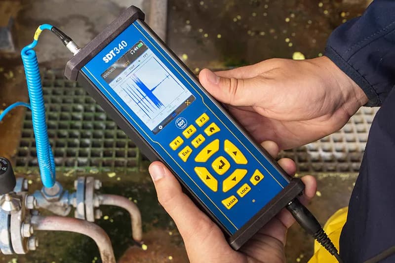
- Bearing ultrasound, lubrication checks and vibration on one route — SDT340: contact and airborne ultrasound sensors, an accelerometer, a built-in infrared temperature sensor and tachometer.
- Pumps where a sensor is hard to mount (submersible, in pits) — Artesis AMT Pro: analysis of motor currents and voltages; the manufacturer lists pump cavitation, unbalance, misalignment and bearing faults among detectable faults.
KEG TRK supplies these instruments in Kazakhstan and helps select a kit for your pump fleet. Price on request.
Sources
- Europump. Pump Vibration Standards Guidelines, 1st edition, July 2013 (ISO 10816-7, ISO 13709, ISO 5199).
- Institute for Standardization of Serbia. ISO/AWI 20816-7 project status.
- Hydraulic Institute. Pump Vibration & Troubleshooting Strategies, Part 2.
- Emerson. Vibration Analysis for Machinery Health Diagnosis.
- ACOEM. Finding Unbalance and Misalignment on a Spectrum.
- Fluke Reliability. Linear vs. Non-Linear Systems Explained, Part 2.
- KSB. Centrifugal Pump Lexicon: Radial thrust.
- Bently Nevada. vb7 Portable Data Collector, Analyzer and Balancer, datasheet 116M5255 Rev. F.
- SDT Ultrasound Solutions. SDT340.
- NVMS (Artesis distributor). Artesis AMT Pro.
Frequently asked questions
Equipment in this article
KEG TRK quotes prices and delivery times to Kazakhstan on request. We will prepare a commercial offer for your application.
vb7 — collector, analyzer and balancer
Dual channel simultaneous recording, two-plane balancing, IP65
SDT340 - Advanced Ultrasound Detector
The most advanced ultrasound detector for collecting, analysing and trending data
Also in this article: Artesis AMT Pro — Portable Electric Motor Tester
Read also
10/10/2026
Causes of Electric Motor Vibration and How to Tell Them Apart
Unbalance, misalignment, looseness, bearings, resonance, rotor and stator faults, driven machine problems. Which spectrum and waveform signs separate one cause from another.
10/14/2026
How to Check an Electric Motor: Step-by-Step Checklist
A motor is checked in two stages: locked out (visual check, megger insulation test, winding resistance), then running (phase currents, temperature, vibration, bearing ultrasound, current signature).
10/10/2026
What Is Machinery Vibration Analysis and How to Start
Vibration analysis checks machine condition from bearing housing vibration: what is measured, route-based vs online monitoring, which faults show in the spectrum, how to start.