
Centrifugal Pump Construction: Six Components and How to Monitor Each
Suction, impeller, shaft seal, bearings, coupling and motor: what fails first in each component and which diagnostic method sees it. SDT340 ultrasound and Artesis electrical signature analysis.
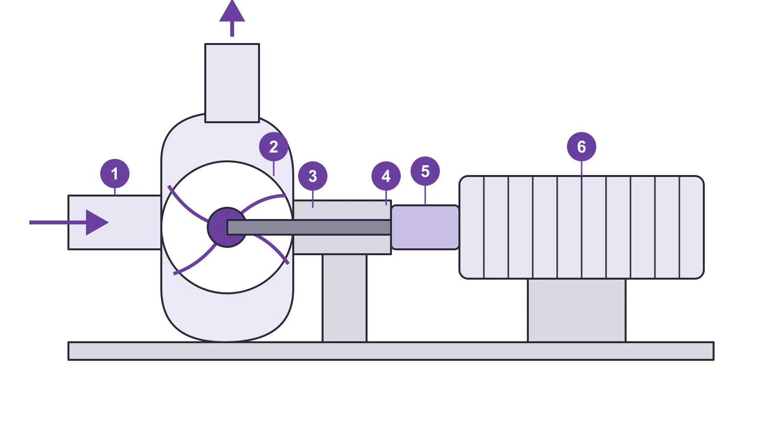
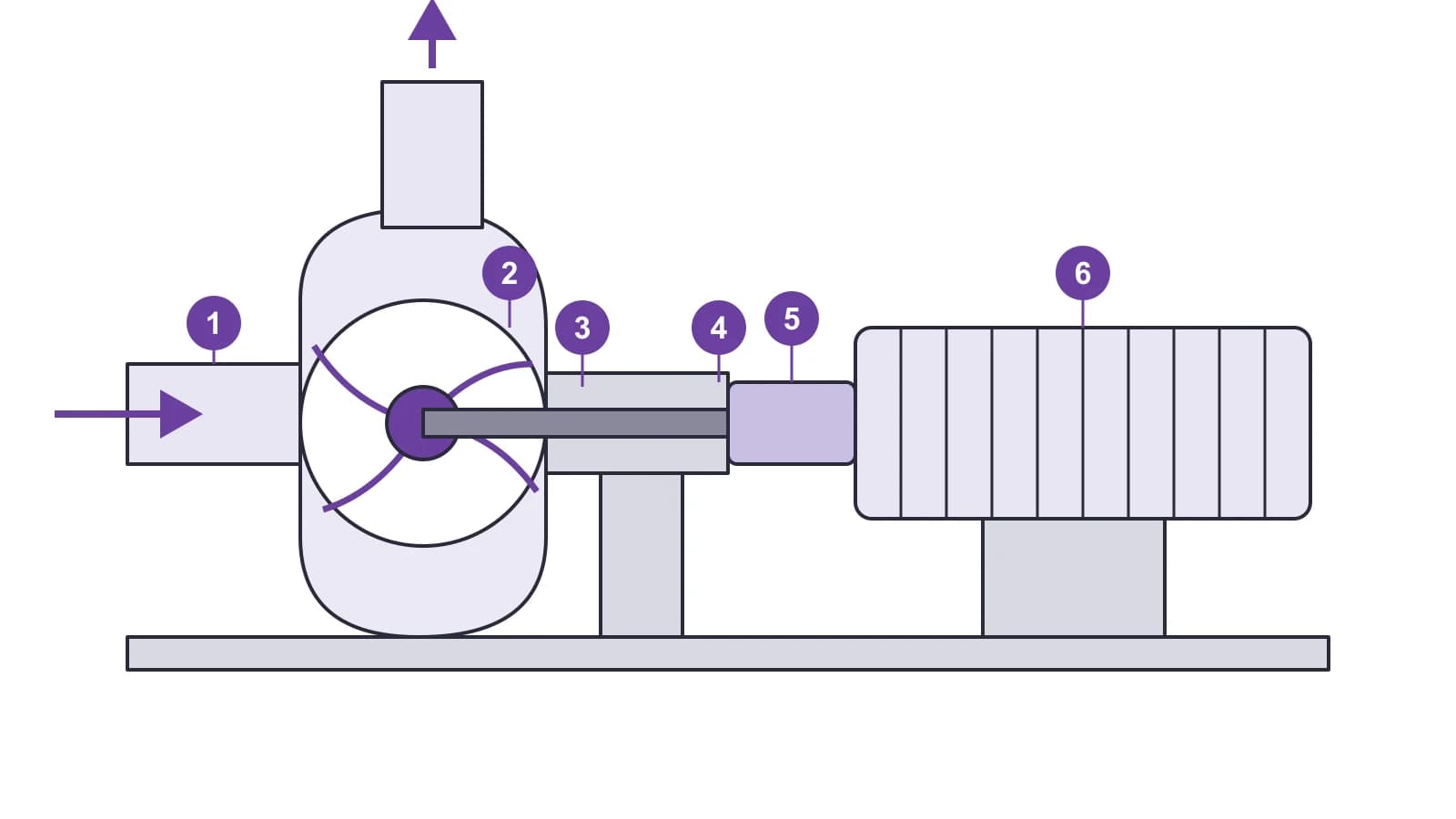
A centrifugal pump looks simple: a motor, a coupling, a bearing housing and a casing with an impeller. But it does not fail as a whole. It fails component by component, and each component gives its own first symptom. If you know what breaks where, and which method sees it earliest, a maintenance program can be drafted in an evening. Below is a short walk through the construction and a monitoring map for SDT340 and Artesis e-MCM.
How the pump works, and why it matters for diagnostics
The impeller rotates and gives the water velocity. The volute casing collects the flow and converts velocity into pressure. Pressure drops at the impeller eye, and water enters from the suction line. Three consequences show up in almost every failure:
- a pump does not move air: air is too light, and an unprimed casing runs dry;
- it is atmospheric pressure, not the pump, that pushes water up the suction line. A column of cold water is theoretically supported at about 10 m; in practice the allowable suction lift is considerably lower, and friction losses in the suction pipe reduce it further;
- rotation direction matters: reverse rotation sharply cuts flow while motor load goes up.
Six components and the first signs of wear
| # | Component | What fails first | How it shows up |
|---|---|---|---|
| 1 | Suction line | Air ingress, clogged strainer, leaking foot valve | Ultrasound: ingress and cavitation noise. ESA: unstable load |
| 2 | Impeller and casing | Cavitation, abrasive wear, clogged passages | Ultrasound: broadband crackle at the inlet. ESA: higher current at the same flow |
| 3 | Shaft seal | Packing too tight or dry, mechanical seal run dry | Ultrasound: rising level at the seal. Visual: leakage |
| 4 | Bearing housing | Too little or too much grease, contamination | Ultrasound and LUBExpert: condition-based lubrication |
| 5 | Coupling | Misalignment, worn elastomer element | Ultrasound at the coupling; ESA: change in current signature |
| 6 | Electric motor | Winding, rotor bars, eccentricity, supply | ESA on the running motor |
1. Suction
The suction line operates under vacuum, so any leak lets air in. A small ingress visibly reduces efficiency; a large one kills the flow altogether. An ultrasonic detector hears the ingress at flanges and fittings before it appears on a gauge. More on air ingress and dry running: article on seals and suction.
2. Impeller and casing
Closed impellers are more efficient on clean water; open and semi-open ones tolerate solids. The impeller type decides what to look for: on clean water, cavitation is the main enemy; on sewage and slurry, abrasion and clogging. Cavitation is covered separately: six signs and combining ESA and ultrasound.
3. Seal
Packing should drip steadily, otherwise it overheats and scores the shaft sleeve. A mechanical seal does not leak, but it cannot tolerate dry running: the pumped liquid cools and lubricates the seal faces. Ultrasound lets you compare the level at the seals of identical pumps and spot an anomaly before leakage appears.
4. Bearings
Ball bearings are greased in portions. Too much grease overheats a bearing as reliably as too little, so "pump it until it stops" is not a method. SDT340 with the LUBExpert option shows whether grease is needed right now and when to stop. Method: ultrasound-based lubrication management.
5. Coupling
The coupling transmits torque and absorbs minor misalignment. The better the alignment, the quieter the pump and the longer the bearings and the coupling itself live. A hidden cause of elastomer failure is often oil reaching the rubber motor mounts and loosening the fixing. See coupling inspection with ultrasound.
6. Motor
The motor drives everything else, and its condition can be assessed without stopping the pump. Artesis e-MCM connects to currents and voltages at the panel and looks for signs of electrical and mechanical faults, including load changes coming from the pump. It also suits submersible pumps, where the machine itself is out of reach: submersible pump diagnostics.
Equipment covered in this article
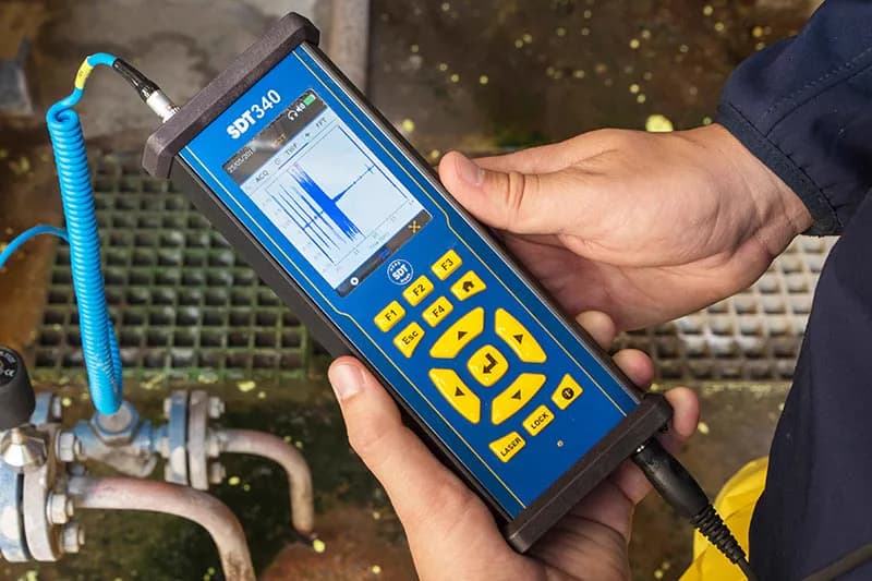
SDT340 - Advanced Ultrasound Detector
The most advanced ultrasound detector for collecting, analysing and trending data
Construction suggests the method
| Pump layout | What to consider |
|---|---|
| Base-mounted end suction, long coupling | All six components are reachable on an ultrasound route |
| Close coupled (motor and pump on one shaft) | No coupling or separate pump bearing housing; ESA is especially useful |
| Between-bearings, split casing | Two supports and two seals: check both ends |
| Vertical in-line | Limited access; some components are easier to watch through ESA |
| Submersible | Ultrasound unavailable; ESA at the panel is the main method |
Building a monitoring program
- Build a pump register with layout, power and process criticality.
- For accessible units, set up an SDT340 route: bearings, seals, coupling, suction; record baselines.
- For critical and remote units, install Artesis e-MCM and connect it to Artesis IoT to see status without a site visit.
- Compare against each pump's own baseline and against identical units, not against an abstract norm.
- Resolve any disagreement between methods at the machine: ultrasound tells you where to look, ESA shows how the load changes.
A 90-day start plan is described here: SDT route in 90 days and e-MCM pilot. Industry example: water utilities and pumping stations.
KEG TRK: SDT and Artesis solutions for pump and motor diagnostics in Kazakhstan. SDT catalog · Artesis catalog
Equipment in this article
KEG TRK quotes prices and delivery times to Kazakhstan on request. We will prepare a commercial offer for your application.
SDT340 - Advanced Ultrasound Detector
The most advanced ultrasound detector for collecting, analysing and trending data
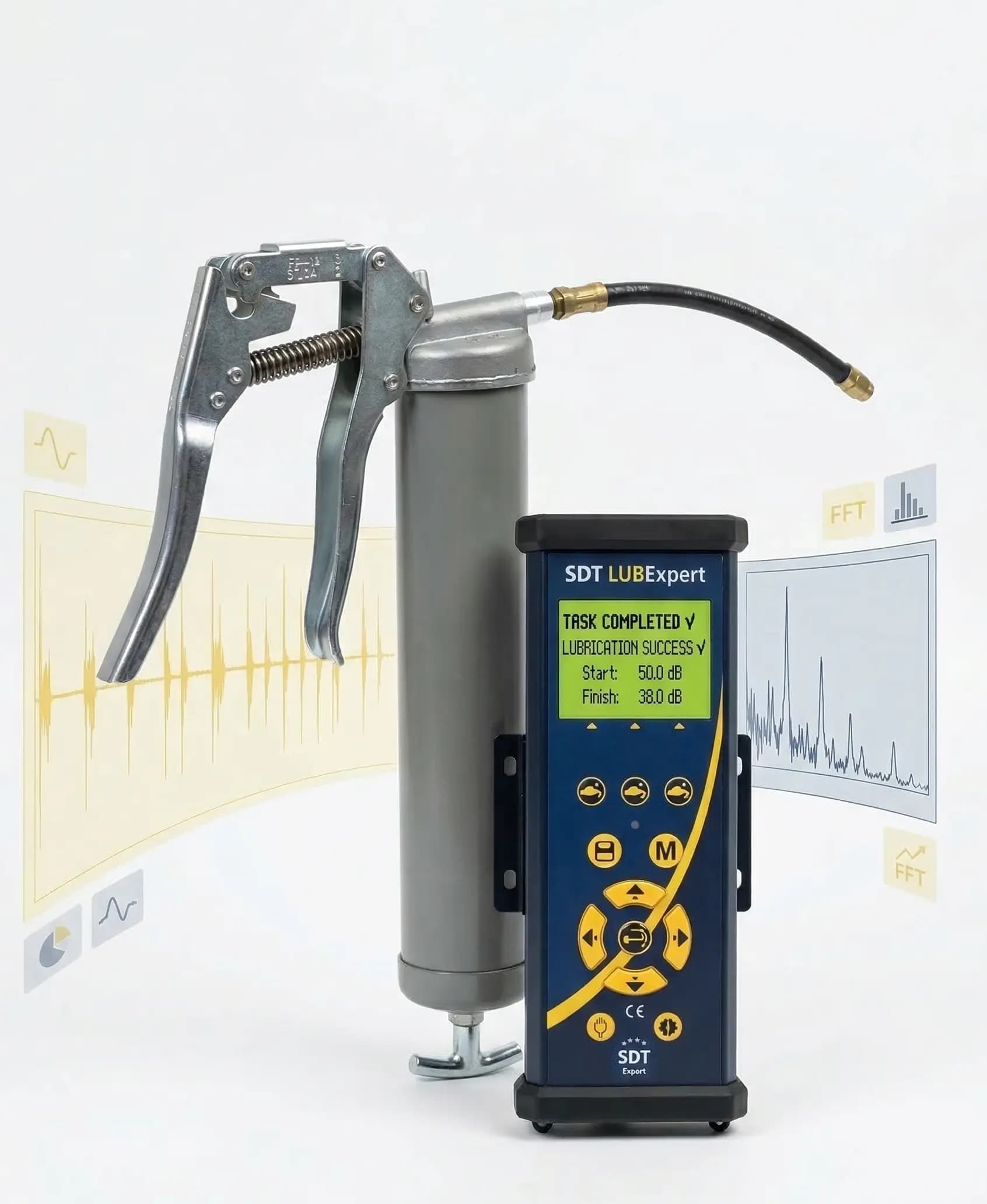
LUBExpert — SDT Ultrasound Bearing Lubrication Assistant
SDT instrument for precision ultrasound-guided greasing of rolling element bearings: tells you when to add grease and when to stop, follows routes from UAS3 and closes…
Also in this article: Artesis e-MCM — Online Sensorless Motor Monitoring
Read also
10/6/2026
Shaft Seals and Suction: Catching Air Ingress and Dry Running in Pumps
Packing or mechanical seal, flushing, air ingress in the suction line and dry running: how it works, how it fails, and how to detect the problem with SDT340 ultrasound and Artesis electrical signature analysis.
7/25/2026
Electric Motor Bearing Lubrication: How Much, Which Grease, How Often
Practical guide to greasing electric motor bearings: grease type, volume, drain, interval — and why “greasing a hot motor” often makes overheating worse.
7/25/2026
Greasing pump and fan bearings: schedule vs condition
How to grease pump and fan bearings at CHP plants, mines and workshops: how they differ from a motor, the typical mistakes, and when a calendar does more harm than good.