

How to Check an Electric Motor: Step-by-Step Checklist
A motor is checked in two stages: locked out (visual check, megger insulation test, winding resistance), then running (phase currents, temperature, vibration, bearing ultrasound, current signature).
An electric motor is checked in two stages. First, with the motor de-energized and locked out: visual inspection, insulation resistance with a megohmmeter, and winding resistance phase by phase. Then with the motor running: phase currents and voltages, frame and bearing housing temperature, vibration, bearing ultrasound and current signature. Below is a step-by-step checklist with IEEE 43 insulation limits.
Checklist summary
| Step | What is checked | Tool | Motor state |
|---|---|---|---|
| 0 | Lockout and absence of voltage | Lock, tag, voltage tester | Off |
| 1 | Appearance, mounting, cooling | Visual | Off |
| 2 | Insulation resistance and polarization index | Megohmmeter | Off, cable disconnected |
| 3 | Winding resistance, phase balance | Micro-ohmmeter | Off |
| 4 | Phase currents and voltages | Clamp meter, analyzer | Running |
| 5 | Temperature | IR thermometer, thermal camera | Running |
| 6 | Vibration | Vibration meter or analyzer | Running |
| 7 | Bearing condition and lubrication | Ultrasound detector | Running |
| 8 | Electrical and mechanical faults from current | Current signature analyzer | Running |
Step 0. Safety: isolation and lockout
Electrical tests on windings are done only on a de-energized motor. The lockout/tagout procedure is described, for example, in OSHA 29 CFR 1910.147:
- Stop the motor normally.
- Isolate every energy source, including winding heaters and control circuits.
- Put a lock and tag on the isolating device.
- Release stored energy: wait for the rotor to stop and secure it against turning from the driven side (pumps and fans can be spun by the flow).
- Verify with a voltage tester that the terminals are dead.
After each megohmmeter test, discharge the winding to ground: it stores charge like a capacitor.
Equipment covered in this article
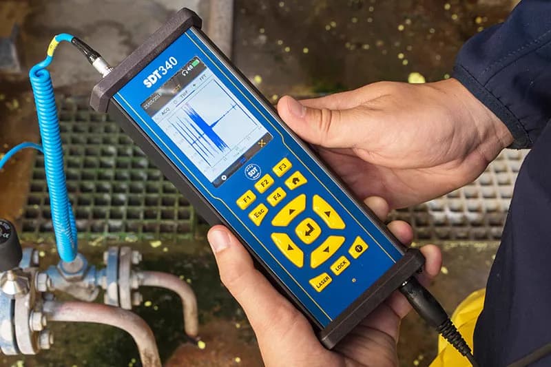
SDT340 - Advanced Ultrasound Detector
The most advanced ultrasound detector for collecting, analysing and trending data
Step 1. Visual inspection
- Check the nameplate against the design: power, voltage, connection, insulation class.
- Inspect the frame for cracks, and the cooling fins and fan cover for dirt and damage: clogged fins reduce cooling.
- Open the terminal box: burnt lugs, darkened insulation, loose nuts, moisture inside.
- Check foundation bolt tightness, the coupling and its guard.
- Turn the shaft by hand if the driven machine allows: binding or grinding points to a bearing or rotor rub.
Step 2. Insulation resistance with a megohmmeter
Disconnect the supply cable so that only the motor is measured. Apply the DC test voltage between the winding leads and the grounded frame and record the reading after 1 minute. Insulation resistance depends strongly on temperature and humidity, so the result is corrected to 40 °C and the winding temperature is recorded.
Test voltage and minimum values from the NETA table based on IEEE 43-2013 (1 minute, corrected to 40 °C):
| Winding rated voltage | DC test voltage | Min.: older windings and other | Min.: AC form-wound, DC armature | Min.: random-wound and form-wound below 1 kV |
|---|---|---|---|---|
| below 1000 V | 500 V | kV + 1 MΩ | 100 MΩ | 5 MΩ |
| 1000–2500 V | 500–1000 V | kV + 1 MΩ | 100 MΩ | — |
| 2501–5000 V | 1000–2500 V | kV + 1 MΩ | 100 MΩ | — |
| 5001–12,000 V | 2500–5000 V | kV + 1 MΩ | 100 MΩ | — |
| above 12,000 V | 5000–10,000 V | kV + 1 MΩ | 100 MΩ | — |
Here kV is the rated line-to-line voltage of the motor in kilovolts. Example: for a 6 kV motor with an older winding the minimum is 6 + 1 = 7 MΩ, while for a modern form-wound winding it is 100 MΩ.
Polarization index (PI) is the ratio of the 10-minute resistance to the 1-minute resistance. IEEE 43 recommends a minimum of 2.0 for all insulation classes except Class A (1.5). If insulation resistance is above 5 GΩ, PI is not considered meaningful. A very high PI (above 8) on older asphaltic or varnished-cambric windings may indicate dried-out, brittle insulation.
One reading is not enough: the trend matters more. If insulation resistance keeps falling from test to test, the winding needs drying, cleaning or repair planning even before the minimum is breached.
Step 3. Winding resistance and phase balance
Stator winding resistance is measured with a micro-ohmmeter using a four-wire connection to cancel the test lead resistance. For a three-phase motor, take three values (between U–V, V–W, W–U, or per phase if all ends are brought out).
- Compare the phases with each other rather than with an abstract limit: a convenient measure is (maximum − minimum) / average × 100 %.
- A spread larger than usual for this motor type points to a loose connection, poor brazing, a turn-to-turn short or an open parallel path.
- Take the allowable spread from the manufacturer's documentation or the repair shop's requirements, and correct readings to the same winding temperature.
Step 4. Start-up, no-load and on-load current
- After the electrical tests, remove the lockout according to procedure and start the motor.
- Check the direction of rotation and listen: a hum turning into jerks can mean a lost phase or unbalanced supply.
- Measure all three phase currents with a clamp meter and the voltages at the terminals. Phase currents should be close to each other; current unbalance with balanced voltage points to a winding or rotor fault.
- Compare the running current with the nameplate rating and with earlier readings at the same load. Rising current at unchanged load is a reason to look for a mechanical cause (bearing, rub, overloaded driven machine).
Step 5. Temperature
Measure the temperature of the frame, bearing housings and terminal box with an IR thermometer or thermal camera. Compare with identical motors at the same load and with earlier readings. The temperature limit is set by the insulation thermal class and the manufacturer's data. A hot spot on the terminal box often means a loose connection; a hot bearing housing means a bearing or lubrication problem.
Step 6. Vibration
Measure RMS vibration velocity at both bearing housings in the vertical, horizontal and axial directions. Compare the result with the zones A–D of the standard: the tables and the assessment procedure are in the article Motor vibration limits per ISO 10816-3. If vibration is high, the cause (unbalance, misalignment, looseness, bearing) is identified from the spectrum.
Step 7. Bearings: noise and ultrasound
A bearing starts to "sound" in the ultrasonic range before overall vibration and temperature rise. A contact ultrasound sensor records the level and signal at each bearing housing, and the result is compared with a baseline. The same measurement shows lack of lubrication and helps avoid over-greasing. Five ways to check a bearing without disassembly are covered in the article How to check a motor bearing without disassembly.
Step 8. Current signature (ESA/MCSA)
Analysis of the currents and voltages of a running motor reveals electrical faults (unbalance, harmonics, rotor and stator problems) and part of the mechanical ones: unbalance, misalignment, looseness, bearing defects and driven-equipment faults. The measurement is taken from the supply circuits with no sensors on the motor, so the method suits submersible pumps and hard-to-reach motors. How vibration analysis, ultrasound and current analysis differ is explained in the article Motor diagnostics: what each method shows.
Common mistakes
- Measuring insulation with the cable still connected and recording it as motor resistance.
- Not recording the winding temperature: readings at 15 °C and 60 °C cannot be compared without correction to 40 °C.
- Forgetting to discharge the winding after the megohmmeter test.
- Assessing vibration with a single reading at one point and no axial direction.
- Checking the motor in isolation from the driven machine: the cause is often in the pump, fan or coupling.
Which instrument to use
- Bearing ultrasound, vibration and temperature with one route instrument — SDT340: according to SDT, it accepts contact and airborne ultrasound sensors and an accelerometer, and has a built-in infrared temperature sensor and tachometer.
- Current signature with no sensors on the motor — Artesis AMT Pro: a portable system for three-phase AC motors and driven equipment, about a 7-minute test, with a report on electrical, mechanical and process faults.
KEG TRK supplies these instruments in Kazakhstan and helps select a kit for your motor fleet. Price on request.
Sources
- OSHA. Control of Hazardous Energy (Lockout/Tagout).
- TestGuy / ANSI/NETA. Insulation Resistance Test Values (motor winding table based on IEEE Std 43-2013).
- TestGuy Wiki. Field Testing of Motors (IEEE 43: polarization index, correction to 40 °C).
- SDT Ultrasound Solutions. SDT340.
- NVMS (Artesis distributor). Artesis AMT Pro.
Frequently asked questions
Equipment in this article
KEG TRK quotes prices and delivery times to Kazakhstan on request. We will prepare a commercial offer for your application.
SDT340 - Advanced Ultrasound Detector
The most advanced ultrasound detector for collecting, analysing and trending data
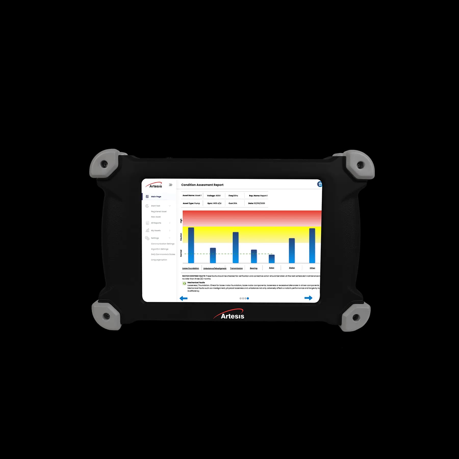
Artesis AMT Pro — Portable Electric Motor Tester
Portable sensorless motor diagnostics with AI analysis — full test in 7 minutes
Read also
10/10/2026
Electric Motor Diagnostics: Which Method Shows What
Vibration, ultrasound, thermography, current analysis (MCSA/ESA), motor circuit analysis (MCA), megohmmeter and oil analysis: which faults each method sees, where it stops and how to combine them.
10/10/2026
How to Check an Electric Motor Bearing Without Disassembly: 5 Methods
Five ways to check a bearing on a running motor: stethoscope, IR thermometer, vibration, ultrasound and current analysis. What each method shows, where it stops, and in what order to use them.
10/10/2026
Broken Rotor Bars: Symptoms and Diagnostics
How a broken rotor bar in an induction motor shows up in current (f ± 2sf sidebands) and vibration (pole pass frequency sidebands), how to calculate these frequencies and check a motor step by step.