
Broken Rotor Bars: Symptoms and Diagnostics
How a broken rotor bar in an induction motor shows up in current (f ± 2sf sidebands) and vibration (pole pass frequency sidebands), how to calculate these frequencies and check a motor step by step.
A broken rotor bar breaks the magnetic symmetry of an induction motor rotor. Stator current shows sidebands at f ± 2sf around the supply frequency; vibration shows pole pass frequency sidebands around running speed. It is diagnosed with current analysis under operating load and confirmed with vibration; on a stopped motor, motor circuit analysis (MCA) is used.
What happens when a bar breaks
A squirrel-cage induction motor rotor consists of bars shorted at the ends by rings. Artesis describes the mechanism: when a bar cracks, the rotor's magnetic symmetry breaks down, and the resulting imbalance induces a small oscillating component in the stator current.
SKF lists the rotor problems that vibration analysis detects:
| Fault | How it shows in vibration (per SKF) |
|---|---|
| Broken or cracked rotor bars | Pole pass frequency sidebands around 1× running speed and its harmonics |
| Bad high-resistance joints between bars and shorting rings | The same; sidebands may also appear around 2×, 3×, 4× and 5× running speed |
| Shorted rotor laminations | Listed by SKF as a rotor problem detectable with vibration |
| Loose or open rotor bars making bad contact with end rings | Vibration and harmonics at rotor bar pass frequency (RBPF), sidebands around RBPF spaced at twice line frequency |
Why it matters
Artesis notes that broken bars do not by themselves cause an induction motor to fail, but the fault mechanism can break parts and cause mechanical damage and winding failure. This affects production and leads to an expensive repair. Among the manifestations of the fault Artesis lists overheating and sparking. Per Artesis, the problem is typical of motors with heavy duty cycles.
Equipment covered in this article
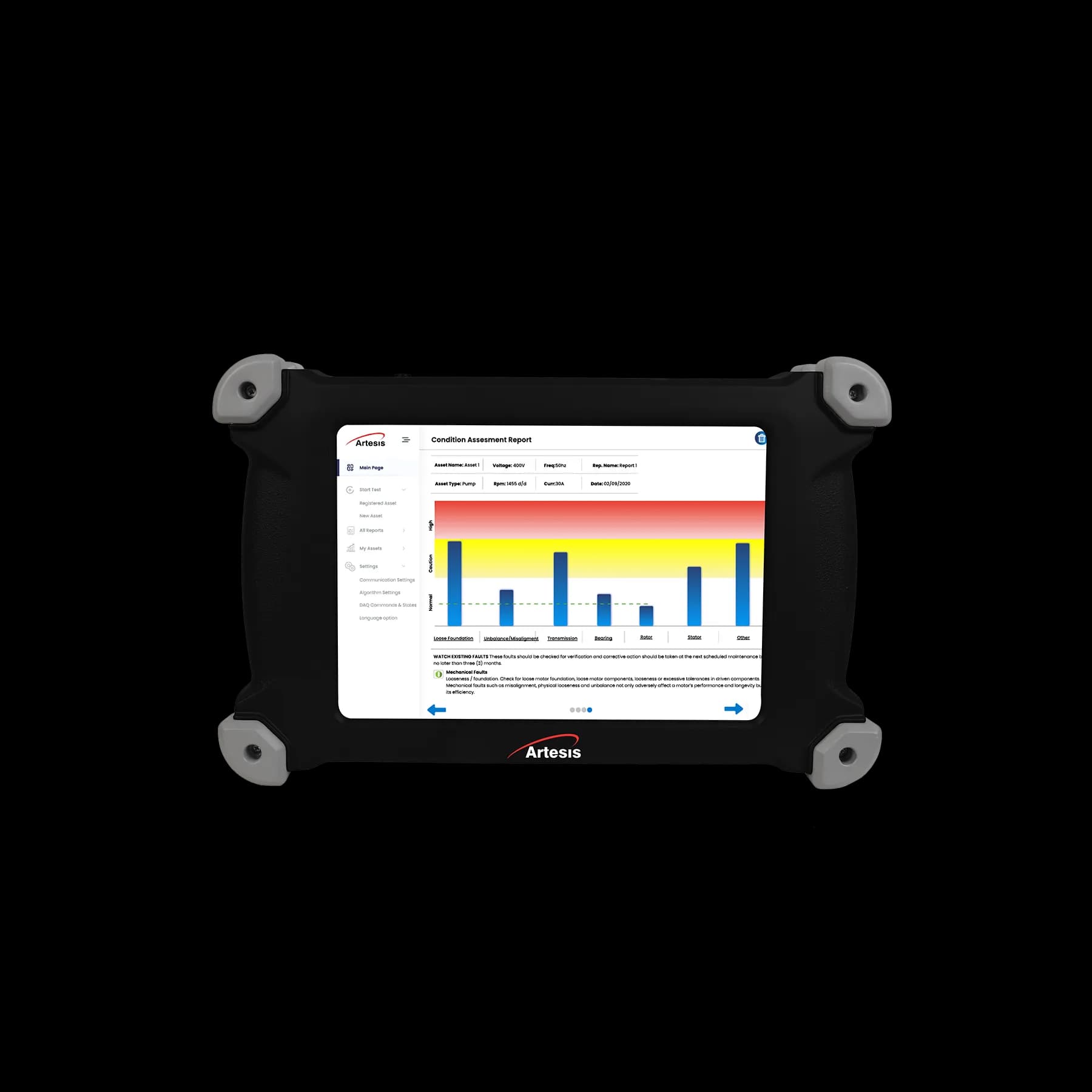
Artesis AMT Pro — Portable Electric Motor Tester
Portable sensorless motor diagnostics with AI analysis — full test in 7 minutes
Symptoms in current (MCSA and ESA)
Artesis calls broken rotor bars the "textbook" fault for current analysis. The symptom is sidebands at
f ± 2sf, where f is the supply frequency and s is the motor slip.
The key caveat is that the symptom depends on load. Per Artesis, the higher the load, the greater the slip and the more pronounced the sidebands, so current analysis works best at representative load. A motor running at no load is not suitable for this check.
Symptoms in vibration
In vibration SKF recommends looking for pole pass frequency sidebands around running speed and its harmonics. SKF gives these formulas:
| Quantity | Formula (per SKF) |
|---|---|
| Synchronous speed Ns, r/min | Ns = 120 · FL / P |
| Slip frequency Fs | Fs = Ns − RPM |
| Pole pass frequency Fp | Fp = Fs · P |
| Rotor bar pass frequency RBPF | RBPF = number of rotor bars · RPM |
Here FL is the line frequency, P the number of poles, and RPM the actual rotor speed. How to read a spectrum and find sidebands is covered in How to read an FFT spectrum.
Worked example
A hypothetical motor: 4 poles, 50 Hz supply, measured speed 1470 r/min.
- Synchronous speed: Ns = 120 · 50 / 4 = 1500 r/min.
- Slip frequency: Fs = 1500 − 1470 = 30 r/min, i.e. 0.5 Hz. Slip s = 30 / 1500 = 0.02.
- Pole pass frequency: Fp = 30 · 4 = 120 cycles/min, i.e. 2 Hz.
- In current, look for sidebands at f ± 2sf = 50 ± 2 · 0.02 · 50 = 50 ± 2 Hz, i.e. at 48 and 52 Hz.
- In vibration, running speed is 1470 / 60 = 24.5 Hz; look for sidebands at 24.5 ± 2 Hz, i.e. 22.5 and 26.5 Hz, and likewise around the harmonics.
The example shows why accurate speed matters: an error of 10 r/min changes the slip frequency in this example by a third, and the sidebands will not be where you look for them. Measure speed with a tachometer instead of taking it from the nameplate.
What it can be confused with
- Stator faults. Per SKF, stator eccentricity, shorted laminations and loose iron produce a high component at twice line frequency (100 Hz on 50 Hz). They are generated in the stator and are not modulated by running speed or slip, so pole pass sidebands may or may not be present.
- Rotor eccentricity. Artesis treats static and dynamic eccentricity as separate faults that are also visible in current.
- Load fluctuations. Sidebands depend on slip, so readings must be compared at the same load.
Step-by-step diagnostics
- Load the motor close to normal operation and wait for steady state.
- Measure actual speed with a tachometer and calculate slip and symptom frequencies.
- Take a current spectrum (MCSA/ESA) and find the f ± 2sf sidebands.
- Confirm with vibration: pole pass frequency sidebands around 1× and harmonics. For loose bars, check the RBPF region.
- Compare with a baseline: earlier readings of this motor at the same load and similar machines. Sideband alarm levels are set by the method of the specific diagnostic system; we do not quote them in this article.
- At a stop, check the rotor with motor circuit analysis (MCA): per Artesis, this de-energized method also detects rotor issues.
- Keep a trend and plan the repair before the fault causes secondary damage.
How current analysis relates to vibration analysis is covered in ESA, MCSA and vibration analysis. An overview of all motor diagnostic methods: Electric motor diagnostics: which method shows what. Other faults visible in current: 5 typical electric motor faults.
What to use
The portable Artesis AMT Pro tester analyses three-phase current and voltage without sensors on the motor; its description lists rotor defects (broken bars) among the electrical faults it detects. A test takes 7 minutes, and direct-on-line, star-delta, soft start and VFD starting are supported. For vibration confirmation and accurate speed measurement, the SDT340 has a 10 Hz – 10 kHz vibration channel and a built-in tachometer.
KEG TRK supplies Artesis motor testers and SDT instruments in Kazakhstan. Price on request.
Sources
- Artesis. What is Condition Monitoring? A Technical Overview (MCSA section). https://artesis.com/condition-monitoring/
- Artesis. Motor Current Signature Analysis. https://artesis.com/motor-current-signature-analysis/
- SKF. Spectrum Analysis: the key features of analyzing spectra (J. Mais), section 12 "Electrical problems": Stator problems, Rotor problems. https://cdn.skfmediahub.skf.com/api/public/0901d1968024acef/pdf_preview_medium/0901d1968024acef_pdf_preview_medium.pdf
- KEG TRK product pages: Artesis AMT Pro, SDT340.
Frequently asked questions
Equipment in this article
KEG TRK quotes prices and delivery times to Kazakhstan on request. We will prepare a commercial offer for your application.
Artesis AMT Pro — Portable Electric Motor Tester
Portable sensorless motor diagnostics with AI analysis — full test in 7 minutes
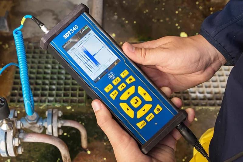
SDT340 - Advanced Ultrasound Detector
The most advanced ultrasound detector for collecting, analysing and trending data
Read also
10/10/2026
Electric Motor Diagnostics: Which Method Shows What
Vibration, ultrasound, thermography, current analysis (MCSA/ESA), motor circuit analysis (MCA), megohmmeter and oil analysis: which faults each method sees, where it stops and how to combine them.
10/10/2026
How to Check an Electric Motor Bearing Without Disassembly: 5 Methods
Five ways to check a bearing on a running motor: stethoscope, IR thermometer, vibration, ultrasound and current analysis. What each method shows, where it stops, and in what order to use them.
10/10/2026
Causes of Electric Motor Vibration and How to Tell Them Apart
Unbalance, misalignment, looseness, bearings, resonance, rotor and stator faults, driven machine problems. Which spectrum and waveform signs separate one cause from another.