

Predictive Maintenance for Airports: Monitoring BHS, HVAC and Escalators from the MCC
How to monitor an airport's critical electric drives without installing sensors on every mechanism: Artesis electrical signature analysis from the motor control center.
An airport operates as a single production system where downtime is extremely costly. Passengers see the check-in desk, the departure board and the gate, but continuity of the whole operation rests on thousands of electric motors: they drive baggage conveyors and sorters, HVAC fans and pumps, escalators, moving walkways, passenger boarding bridges and other support equipment.
A single drive failure rarely stays a local event. A stopped conveyor can overload a neighbouring section of the baggage handling system, a faulty fan can push a climate unit out of its design mode, and an unplanned escalator stop can change passenger flow. A technical problem quickly turns into an operational one — manual workarounds, queues, delays and extra load on ground handling staff.
That is why an airport needs more than a fast response to a failure that has already happened — it needs early visibility into a fault that is still developing. Artesis solutions monitor drive condition through supply currents and voltages, directly from the motor control center (MCC), without requiring a vibration sensor on every mechanism.
Why traditional inspection is often not enough
Scheduled inspections, planned component replacement and vibration analysis remain an important part of maintenance. But in airport infrastructure these methods run into practical limits.
- Equipment is spread across a large site. Drives sit in baggage handling galleries, plant rooms, on the roof, behind fencing and inside enclosed machines.
- Access to the mechanism is restricted. Taking a measurement means arranging safe access, stopping a section, or working inside a short maintenance window.
- Wired sensors on every point are not always justified. Thousands of measurement points mean cable runs, installation, upkeep of the sensors themselves and a separate data-collection infrastructure.
- Periodic rounds leave gaps between readings. A fast-developing defect can appear right after the last check and go unnoticed until the next route.
- Identical units run in different regimes. Conveyor load changes with passenger flow, fan load changes with weather and terminal mode. Assessing condition without load context can produce false conclusions.
The goal is not to replace vibration, ultrasound or thermal inspection, but to extend monitoring coverage. Electrical parameters are available in the MCC — a controlled area where the motor supply and control circuits are already concentrated.
How the motor becomes a sensor for the whole drive
As a mechanism runs, changes in torque and load show up in the current it draws. Electrical faults in the motor itself also change the shape of the currents and voltages. Electrical Signature Analysis (ESA) extracts these changes and matches them against known fault signatures.
Artesis e-MCM connects to the measurement circuits in the MCC and continuously analyses three-phase currents and voltages. No separate sensor needs to be mounted on the motor housing, bearing or gearbox for each monitored parameter. The motor itself becomes the measurement transducer: mechanical and process changes in the drive train modulate its electrical signature.
In simplified form the process looks like this:
- Current transformers and voltage circuits feed the motor's supply data into the system.
- The system analyses the electrical signature together with the operating load.
- Current readings are compared against the baseline and trend established for that specific unit.
- When a deviation persists, the system raises a diagnostic alert for equipment to be checked.
- A technician confirms the cause with a targeted inspection and schedules the work for a suitable maintenance window.
This approach is especially useful where the motor and driven mechanism are physically hard to reach while the MCC sits in a safe, accessible room. It also lets you observe not just the motor itself but load changes coming from the connected mechanism.
Equipment covered in this article
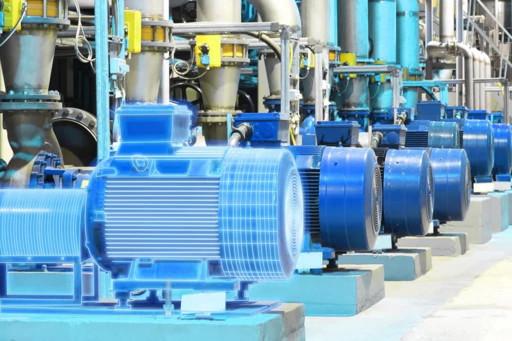
Artesis e-MCM — Online Sensorless Motor Monitoring
Online sensorless electric motor monitoring with AI and digital twin
Which airport assets can be brought into the monitoring programme
The set of detectable fault signatures depends on the drive's design and duty cycle. A practical programme is best built around the consequences of a failure, not just motor power.
| System | Typical electric drives | What to watch for |
|---|---|---|
| BHS — baggage handling | Conveyors, sorters, elevators, carousels | Overload, jamming, imbalance, transmission, bearing and motor faults |
| Terminal and plant-room HVAC | Fans, pumps, compressors, cooling towers | Load changes, imbalance, impeller fouling, bearing wear, electrical faults |
| Escalators and moving walkways | Main drives, gearboxes, auxiliary motors | Rising mechanical load, transmission and bearing issues, duty-cycle mismatch |
| Pumping systems | Water supply, drainage, heating and cooling | Off-normal operation, cavitation signs, blockage, pump and motor wear |
| Passenger boarding bridges and auxiliary mechanisms | Travel, lift and ventilation drives | Overload, load asymmetry, mechanical resistance, electrical faults |
For escalators, moving walkways and other equipment subject to mandatory safety requirements, condition monitoring supplements — but never replaces — the built-in safety systems, scheduled checks and manufacturer requirements.

What faults ESA helps detect
A single monitoring channel can flag several classes of problems at once.
Mechanical condition
Changes in shaft torque show up in motor current. From the shape and progression of these deviations you can detect signs of imbalance, misalignment, loose components, bearing problems, and belt or gearbox transmission issues. For BHS, rising resistance-to-motion signals are especially valuable — fouling, a jamming roller or an overloaded section often appear well before a line comes to a full stop.
Electrical condition
Three-phase analysis tracks current and voltage asymmetry, stator and rotor condition, supply deviations and overload conditions. This makes it possible to separate a fault in the motor itself from a problem coming from the driven mechanism or the electrical supply.
Process behaviour
Load is not only a motor diagnostic parameter — it is also an indicator of process performance. For a fan, a load change can point to a dirty filter or impeller; for a pump, to a shift in hydraulic conditions; for a conveyor, to overload or increased resistance. A trend makes it possible to spot slow degradation that a single measurement would miss.
It is important to interpret an alert correctly: ESA points to the character and progression of a deviation, and the final repair decision is made with the operating regime, the asset's history and the results of a confirming inspection all taken into account.
Why monitoring from the MCC fits an airport
No sensor on every mechanism
The core measurements are taken in the electrical cabinet. This cuts down the work needed directly in the baggage handling gallery, at height, in noisy areas, or inside enclosed equipment, and measurement points can be maintained centrally.
Continuous visibility on critical drives
The stationary e-MCM system watches equipment between scheduled rounds. Maintenance staff get a trend instead of a single snapshot, and can tell a short-lived change in operating mode apart from a defect that is steadily developing.
Context of actual load
Load data lets you assess equipment under real operating conditions. For an airport with pronounced daily and seasonal peaks this matters a great deal: a current rise during peak passenger flow should not, on its own, be read as a fault.
Scaling by criticality
You do not need to move the whole fleet onto continuous monitoring at once. Critical drives can be connected to e-MCM, while the portable Artesis AMT Pro covers periodic checks on less critical equipment. Both approaches are built on the same electrical-parameter analysis, so the programme can be scaled up step by step.
One picture for the reliability team
Artesis IoT brings together data from monitored assets so specialists can prioritise by equipment condition instead of scanning separate route logs. This is particularly useful for an airport with several terminals, plant buildings and remote assets.
Building a rollout programme
An effective project starts not with a channel count, but with a map of operational risk.
1. Build a drive register
For every motor, record its purpose, power, starting method or VFD, its connection point in the MCC, duty cycle, backup availability and the operational impact of a failure. It helps to tie a motor not just to an asset tag, but to a specific BHS section, an air-handling unit or a terminal zone.
2. Rank criticality
Priority goes to assets whose failure could stop baggage flow, disrupt a mandatory climate condition, restrict a passenger route or trigger a long recovery. Take into account bypass availability, standby units, spare parts and the time it takes a repair crew to reach the asset.
3. Review the electrical architecture
Before installation, confirm the supply diagrams, available measurement circuits, presence of VFDs, spare space in the cabinets and electrical safety requirements. Work inside the MCC must be carried out by qualified personnel in line with the project documentation and the site's operating procedures.
4. Run a pilot on a representative group
A pilot should include different load types — for example, a BHS conveyor, a fan, a pump and a passenger-infrastructure drive. This mix lets you validate data quality on both steady and variable load, exercise the alerting workflow, and define who confirms each alert.
5. Build a baseline and set up the response process
The algorithm needs a period of normal operation to build its comparison baseline. In parallel, the team defines the event-handling route: who receives the alert, what data they check, when the inspection happens, and how the result feeds into the CMMS/EAM or the maintenance log.
6. Measure operational outcomes, not alert counts
Useful project metrics include the reduction in unplanned stoppages, the share of confirmed diagnostic events, the time from alert to inspection, the number of jobs moved from emergency to planned work, and fault recurrence. For energy efficiency, track sustained load changes for comparable operating regimes separately.
How to split diagnostic methods
The most reliable programme does not pit technologies against each other — it gives each one the role it is best suited for.
- Artesis from the MCC provides broad, continuous coverage of electric drives, especially the remote and hard-to-reach ones.
- Vibration analysis gives detailed confirmation of a mechanical fault where safe access exists and component-level localisation is needed.
- Ultrasound helps check bearings, leaks and electrical discharge during targeted inspections.
- Thermal imaging detects overheating in connections, busbars, switchgear and other elements of the electrical distribution system.
- Built-in automation and protection react immediately to hazardous conditions and remain a mandatory part of the safety system.
In this arrangement, ESA becomes the first layer of early detection and prioritisation. Specialists direct their time and more precise methods to where a trend already shows a deviation, instead of inspecting the whole fleet at the same frequency.
From emergency repair to managed intervention
The goal of predictive maintenance is not to predict the exact failure date of every motor. Its practical value lies elsewhere: giving the operations team a signal early and clear enough to check the asset, order the parts it needs and carry out the work in an agreed window.
For an airport, this means fewer sudden switches to manual baggage handling, fewer unplanned restrictions on passenger infrastructure, and a more predictable workload for technical teams. Monitoring directly from the MCC helps extend this approach across a large drive fleet, including the points where traditional sensors are difficult or expensive to install.
Also read: how the Artesis Omnisight unified ESA platform works · Artesis three-tier PdM strategy · 90-day e-MCM pilot · motor monitoring product catalogue
KEG TRK helps design an Artesis monitoring architecture, run a pilot project and build the response process for diagnostic events. Discuss your airport project.
Equipment in this article
KEG TRK quotes prices and delivery times to Kazakhstan on request. We will prepare a commercial offer for your application.
Artesis e-MCM — Online Sensorless Motor Monitoring
Online sensorless electric motor monitoring with AI and digital twin
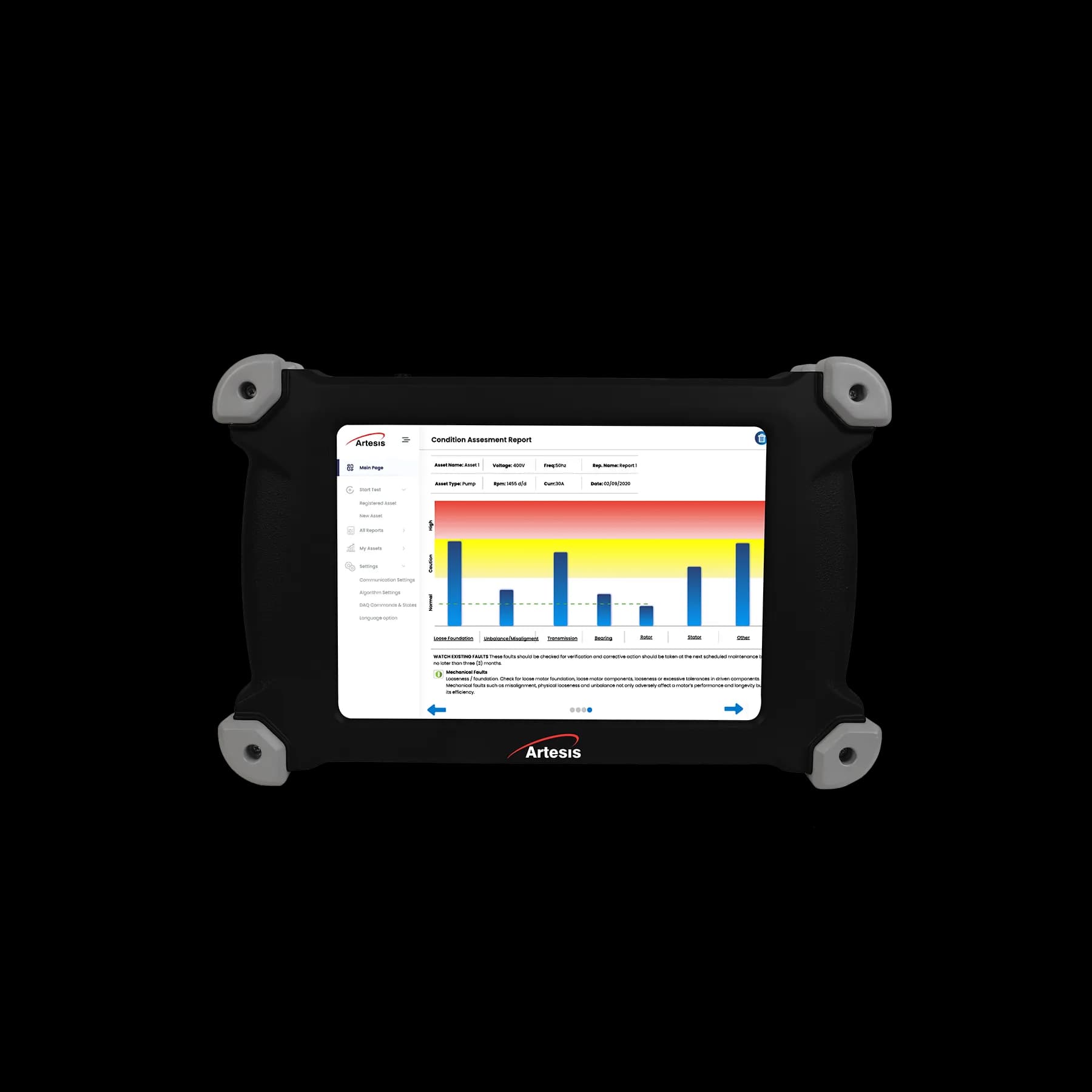
Artesis AMT Pro — Portable Electric Motor Tester
Portable sensorless motor diagnostics with AI analysis — full test in 7 minutes
Also in this article: Artesis IoT — Cloud Monitoring Platform
Read also
7/17/2026
Rolling mill monitoring: ESA for auxiliary and main drive motors
At Kazakhstan's rolling mills vibration covers the large stands, but the fleet of roller-table, coiler and cooling-pump motors is often left without predictive monitoring. How Artesis e-MCM and AMT Pro complement vibration.
7/17/2026
Pump cavitation: how ESA and ultrasound complement each other
SDT ultrasound hears bubbles collapsing on the pump casing; Artesis ESA sees the efficiency drop and the load anomaly in the current. A combined method for CHP plants, water utilities and mines — without nuisance shutdowns.
6/30/2026
Artesis e-PCM for Diesel Generators: Backup Power Monitoring Without Shaft Sensors
Diesel gensets at CHPs, oil & gas sites and data centres: how e-PCM monitors engine and generator from output current and voltage — early warning before grid failure exposes a dead unit.