
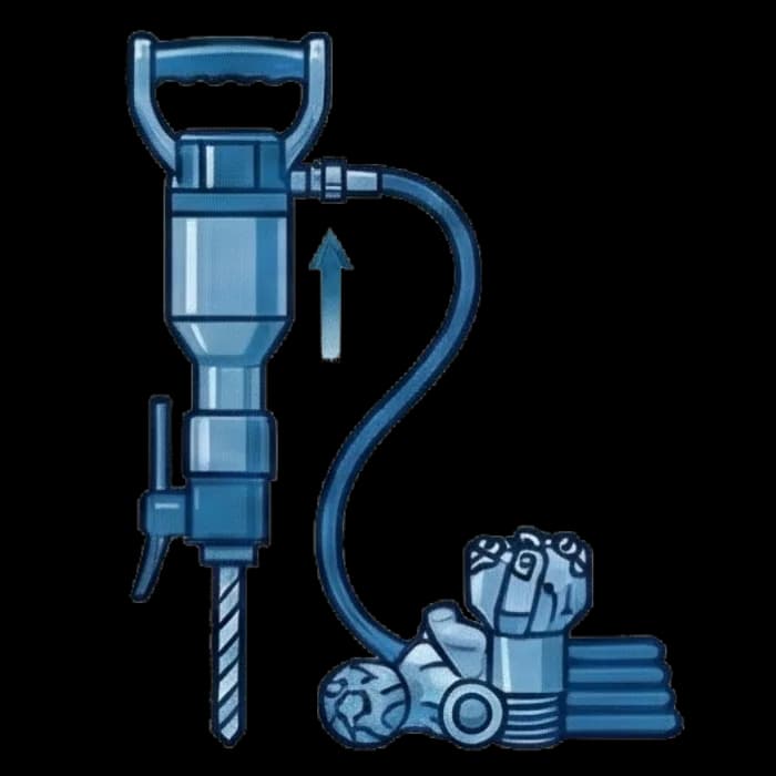
Pneumatic Rock Drills and Drilling Equipment: Selection and Maintenance
How to choose an OZBIO pneumatic rock drill, keep wear-part replacement intervals, and why compressed-air leaks quietly drain tool life and drilling performance.
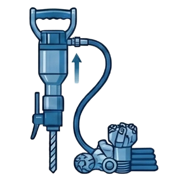
The pneumatic rock drill remains the workhorse of drilling operations in mining, open-pit quarries, and underground development — the one place where reliability and field repairability outweigh any electronic sophistication. But behind the apparent simplicity of the design sits a set of rules: the wrong model choice, a missed rotation-bushing replacement interval, or a plain leak in the compressed-air line can turn a healthy drill into a source of downtime within weeks. Below is a practical guide to selecting and maintaining OZBIO pneumatic drilling equipment for mining engineers and procurement teams.
Classes of pneumatic drilling tools
Before comparing models, it matters which class of equipment the job actually calls for. Hand-held, telescopic, mounted, and auxiliary pneumatic tools sit in different weight classes with different maintenance logic.
| Tool class | Typical application | Example models | Key feature |
|---|---|---|---|
| Hand-held perforators (PP) | Manual blast-hole drilling, confined headings | PP36V2, PP36U, PP54V2, PP63V2 | Compact, works without a feed support |
| Telescopic perforators (PT) | Drilling with a pneumatic feed leg, up-holes and down-holes | PT38B, PT48A, PT75 | Power unit unified with PP75 |
| Series 75 perforators | Modernized line for open pits and underground work | PP75, PT75 | Unified parts, patented ratchet assembly |
| Pneumatic motors | Drive for drill carriages, winches, rotators | OZBIO pneumatic motor line | Compact torque with no electrics in a hazardous zone |
| Pneumatic saws | Cutting metal and materials during equipment install/removal | OZBIO pneumatic saws | Pneumatic drive where sparking is not acceptable |
The full range of pneumatic tools and spare parts is available in the OZBIO pneumatic equipment section.
Checklist before choosing a model
Before writing up a purchase requisition, procurement and the chief mechanic should put five parameters in writing — it saves time cross-checking with the supplier and reduces the risk of buying a tool that does not match the job:
- Hole diameter and depth per the drill-and-blast design.
- Rock drillability class (Protodyakonov strength scale or an equivalent).
- Feed method — hand-held, on a pneumatic feed leg, or on a telescopic feed.
- Presence and parameters of the water-flushing system (dry drilling sharply increases dust loading and bit wear).
- Actual operating pressure and air flow at the connection point — not the compressor's rated value, but what is measured at the end of the line.
The last point is the one most often skipped, and it is exactly the one that determines whether the chosen drill actually delivers its rated output at a given horizon or heading.
Hand-held PP-series perforators: when they make sense
PP-series pneumatic portable perforators are the base tool for drilling 32–63 mm blast holes in rock of varying strength. PP36V2 and PP36U suit tight headings and confined-space work. PP54V2 and PP54VB2 are universal mid-class models. PP63V2, PP63S2, and PP63VB2 are heavy drills for large-diameter holes and higher-strength rock.
Selection criteria for the PP series:
- Hole diameter and depth. The larger the hole diameter, the higher the impact energy required — moving from PP36 to PP54 or PP63 should be driven by this parameter, not by "buying headroom for later."
- Rock drillability. For above-average strength rock, "B"-index models (PP54VB2, PP63VB2) give a more stable penetration rate thanks to a reinforced impact mechanism.
- Ventilation and dust conditions. Models with automatic water flushing (a series 75 feature) cut dust generation and extend bit life.
- Weight and ergonomics. A hand-held perforator over 25 kg needs a pneumatic feed support — otherwise the operator physically cannot sustain a full shift.
Equipment covered in this article
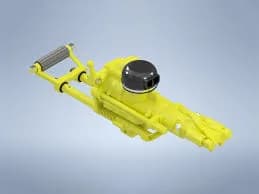
Pneumatic Portable Rock Drills, PP Series
Pneumatic portable rock drills for drilling and mining operations. Models: PP63V2, PP54V2, PP54VB2, PP36V2, PP36U, PP63S2, PP63VB2
Telescopic perforators and the Series 75: standardization as savings
Series 75 perforators (PP75 and PT75) are OZBIO's current generation. Their main practical advantage for a supply department is a unified power unit: the cylinder, striker piston, valve group, rotation screw, and barrel assembly are interchangeable between the hand-held and telescopic versions. That means the spare-parts stock can shrink by nearly half compared to servicing a mixed fleet of older models.
Series 75 also borrows parts from the PP54 perforators (valve group, vibration damper, chuck) — this lets sites use existing stock when switching to the new line instead of writing it off.
Practical benefits of Series 75 in operation:
- The rotation-spline bushing is field-repairable. A worn bushing element can be replaced right at the work site, without sending the assembly to a repair shop.
- Automatic water flushing engages in sync with the drilling mode — removing the human factor ("forgot to turn on the water"), which directly protects the bit and bushing from overheating and abrasive wear.
- The patented spring-free ratchet assembly cuts the jamming frequency typical of spring-based equivalents when cuttings get into the mechanism.
- Smooth feed-force adjustment on the PT75 lets the operator adapt to changing rock strength along the hole without stopping drilling.
Auxiliary pneumatic equipment on a drilling section
A perforator rarely works alone. Three groups of auxiliary equipment determine a drilling crew's real output just as much as the drill itself:
- Pneumatic feed legs (models P1, P2, P3) — advance the perforator into the face and take the physical load off the operator. Without a correctly matched feed leg, a telescopic perforator either fails to reach its rated output or wears out its bushing faster due to misaligned feed.
- Chucks / shanks — the connecting element between the perforator and the drill rod. A mismatch between the chuck and the perforator's bushing is one of the most common causes of premature wear in the rotation-spline assembly and lost impact energy.
- Pneumatic motors and pneumatic saws — the section's auxiliary tools: driving carriages and rotators, cutting metal during support and piping installation. Their advantage underground is no sparking and reliable operation in wet, dusty conditions where power tools need extra protection.
Wear parts: where a perforator's service life actually goes
A pneumatic perforator is a high-cycle-rate impact mechanism, and part of it is designed for scheduled replacement, not "run to failure." The rule is simple: the sooner a worn part is replaced, the less damage it does to the parts around it.
| Assembly / part | Typical replacement interval | Sign of end-of-life wear | Consequence of skipping replacement |
|---|---|---|---|
| Drill bit / rod | per tool manual, or when dull | drop in penetration rate, more air consumed per meter drilled | overheated shank, broken rod |
| Rotation-spline bushing | 150–300 running hours (depends on rock abrasiveness) | play on the rotation axis, uneven bit rotation | accelerated wear of the barrel and shank |
| Valve group (distributor) | 300–500 running hours | drop in impact power, a "flattened" impact sound | 20–30% drop in drilling output |
| Striker piston | based on inspection during scheduled teardown | chipped striking face, galling on the working surface | cylinder failure on the next cycle |
| Vibration damper | seasonal check, replace when resilience is lost | rising vibration at the handle | operator occupational injury, faster housing wear |
| Seals and gaskets | at every scheduled teardown | pressure loss in the chambers, air leaking from the housing | lost impact energy, water ingress into internal cavities |
| Feed ratchet assembly | checked at scheduled maintenance, replaced on wear | feed slippage | unstable penetration rate |
These intervals are a planning benchmark for spare-parts stock — actual service life depends on rock abrasiveness, the water quality in the flushing system, and, importantly, the quality of the compressed air itself.
Why compressed-air quality determines a perforator's service life
A pneumatic perforator is designed to run at a specific operating pressure (typically 5–6 bar at the tool inlet) and a specific air flow. Any deviation from the design parameters hits component life faster than rock abrasiveness does:
- Moisture in the air. Condensate reaching the valve group washes out lubrication and corrodes precision friction pairs — the valve and cylinder lose their seal within weeks.
- Too little or too much oil mist. Insufficient lubricating oil in the air line sharply accelerates wear on the bushing and striker piston; too much oil, conversely, clogs exhaust ports and reduces impact frequency.
- Mechanical contaminants. Rust and scale from piping act as an abrasive inside the valve group — an assembly rated for 300–500 running hours can fail three times faster.
- Pressure drop at the end of the line. A perforator getting 4 bar instead of 6 loses up to a third of its impact energy — while looking outwardly fine, leading crews to blame low penetration rates on "tougher rock" or "an old tool."
That last point — pressure drop at the actual point of use — turns out in practice to be the most underrated cause of low output on a drilling section.
Diagnostics: tool wear or an air-supply problem?
The two causes are hard to tell apart by eye — the symptoms look alike. The table below helps narrow the search before a perforator is pulled off the face and sent for repair.
| Symptom at the face | Likely cause — tool wear | Likely cause — air supply | What to check first |
|---|---|---|---|
| Drop in penetration rate | worn bit, worn valve group | insufficient inlet pressure, a long/narrow hose | pressure gauge right at the tool |
| A "dull" impact sound | chipped or worn striker face | pressure drop, flow diverted to a neighboring consumer | pressure while several perforators run at once |
| Play / runout on the bit | worn rotation-spline bushing | — | disassemble and measure the bushing |
| Perforator "won't pull" when the compressor starts | — | insufficient compressor output, network leaks | total network demand vs. rated compressor output |
| Unstable power through the shift | worn housing seals | rising number of leaks as pipework warms up and new draw-off points open | ultrasonic survey of the line |
| High air consumption per meter drilled with an outwardly sound tool | internal leaks through seals | leaks in the distribution network upstream of the tool | compare actual vs. rated consumption for the tool |
If several perforators on a section lose power at the same time with no visible mechanical fault, that is almost always a signal about the compressed-air network, not the tools.
Leaks in the compressed-air network: the hidden cause of lost power
This deserves its own section, because this cause of lost output rarely makes it onto a pneumatic-tool maintenance schedule — even though it should.
A mine site's compressed-air network is tens or hundreds of meters of piping, threaded joints, quick-connect couplings, and hoses laid out in harsh conditions: vibration, temperature swings, mechanical damage from moving equipment. Every loose joint is a source of continuous leakage, and on a noisy production section these leaks are physically inaudible to the human ear.
The economics of leaks are covered in general terms in the article Compressed Air Leaks: Money Going Out the Pipe: a single 3 mm leak at 7 bar costs a site thousands of dollars in electricity every year. But for a drilling section there is a second, equally important consequence: every leak between the compressor and the perforator is a direct loss of working pressure at the point of use. The compressor can be running normally and total output can match the nameplate, while a perforator at the far end of the line is starved of pressure and "underperforming" for reasons the crew wrongly blames on tool wear.
Finding such leaks by ear on a working section is impossible — the turbulent noise of the perforators and the compressor house completely masks the hiss of a leak. The solution is a periodic ultrasonic survey of the compressed-air network using a dedicated leak detector that picks out the high-frequency ultrasound of turbulent flow through the plant noise. Equipment and methodology for this kind of diagnostics are covered in the ultrasonic leak detection section from SDT — KEG TRK's partner for ultrasonic diagnostics.
The practical takeaway for the chief mechanic's office: a pneumatic-tool maintenance programme without a periodic leak audit of the supply network is only maintaining half the system. The other half of a perforator's service life is lost not at the face, but in a pipeline nobody checks.
Where a drilling section typically loses air
- Quick-connect couplings on portable hoses — the most vulnerable point given the perforator's constant movement between faces.
- Threaded joints on fixed pipework after vibration loading from the running compressor and the drill itself.
- Gaskets past their service life at demountable joints after line repairs.
- Unclosed or faulty valves on temporary branches to neighboring faces.
- Worn high-pressure hoses with hairline cracks along their length — invisible to the eye but a real source of flow loss.
None of these defects is visible to the naked eye or audible over a running perforator — which is exactly the practical case for an ultrasonic rather than a visual inspection.
A practical perforator maintenance programme
Below is a minimal framework applicable to the PP series, Series 75, and pneumatic auxiliary tools generally.
| Frequency | Tool-side work | Air-network-side work |
|---|---|---|
| Every shift | Visual check, check pressure at the tool, verify water/lubrication feed | Inspect visible joints, drain condensate from moisture separators |
| Weekly | Check bushing play, condition of the shank and bit | Check pressure at remote points of use |
| Monthly | Partial teardown to inspect the valve group and vibration damper | Visual walk-down of the line, check quick-connect couplings |
| Quarterly | Full teardown, inspect the striker piston and cylinder, replace seals | Ultrasonic leak survey of the network |
| By running hours / per manual | Scheduled bushing and valve-group replacement on wear | Repair identified leaks, re-check pressure after repair |
This schedule does not replace OZBIO's factory maintenance manuals — it supplements them with oversight of the air-supply system, the part of the fleet that is not formally "a tool" but determines how much of the rated service life the tool actually gets.
The operator's and mechanic's role
A schedule on paper does not work without someone carrying it out on site. Two simple organizational steps are usually enough to make it stick:
- Assign pressure checks at the tool to the operator, not to the power engineer who visits once a shift. A pressure gauge at the perforator inlet is a cheap instrument, but it is the first thing to flag a pressure drop in the line.
- Train the section mechanic to recognize typical bushing and valve-group wear by sound and by play — most PP- and Series-75 faults can be diagnosed without a full teardown once you know what to listen and look for.
Common operating mistakes worth avoiding
- Choosing a perforator "by eye," without calculating hole diameter and rock strength. The result is either underdrilling from insufficient impact energy, or accelerated wear on an oversized model where a light PP36 would have done the job.
- Skimping on the pneumatic feed leg. Holding a telescopic perforator by hand misaligns the bushing and shank — an assembly rated for hundreds of running hours wears out several times faster.
- Putting off teardown until the tool fully stops working. Scheduled partial teardown of the valve group is cheaper than replacing a cylinder and striker piston after catastrophic wear.
- Mixing chucks and bushings from different series "based on what's in stock." A mismatch in fitting dimensions is a common cause of accelerated play that gets blamed on "poor-quality parts."
- Monitoring the compressor house but not the distribution network itself. A compressor's rated output says nothing about actual pressure at the end of a 300-meter line with a dozen unaccounted-for leaks.
Conclusion
A pneumatic perforator's service life comes down to three factors: the right model choice for drilling conditions, discipline in replacing wear parts on schedule, and — most often overlooked — the quality and stability of the compressed air at the tool inlet. The OZBIO PP and Series 75 lines, pneumatic motors, pneumatic saws, chucks, and feed legs form a complete drilling-section package, but their combined output is limited by the weakest link — which is often not the perforator itself, but a leaking line. A regular ultrasonic audit of the compressed-air network is not a separate task for the energy department; it is a natural extension of the drilling-tool maintenance programme — it saves electricity at the compressor house and, at the same time, gives the perforator back the working pressure you already paid for.
Equipment in this article
KEG TRK quotes prices and delivery times to Kazakhstan on request. We will prepare a commercial offer for your application.
Pneumatic Portable Rock Drills, PP Series
Pneumatic portable rock drills for drilling and mining operations. Models: PP63V2, PP54V2, PP54VB2, PP36V2, PP36U, PP63S2, PP63VB2
Pneumatic Motors
Pneumatic motors for industrial applications
Also in this article: Pneumatic Saws
Read also
10/13/2026
Acoustic Camera: What It Is and How It Works
How an acoustic camera with a MEMS microphone array shows an ultrasound source on video, what beamforming is, which tasks it handles and where the method has limits.
10/13/2026
Thickness Gauging Through Paint: Echo-to-Echo and THRU-COAT Modes
Why a standard gauge overstates painted steel thickness, how echo-to-echo and THRU-COAT remove the coating, which transducers they need, thickness ranges and temperature limits.
10/13/2026
Ultrasound or thermal imaging for electrical equipment: which to choose
A thermal camera sees heat, which appears late, once enough current flows. Ultrasound hears corona, tracking and arcing at any stage of discharge. That is why SDT recommends using both methods.